- Network Theory - Home
- Network Theory - Overview
- Example Problems
- Network Theory - Active Elements
- Network Theory - Passive Elements
- Network Theory - Kirchhoff’s Laws
- Electrical Quantity Division Principles
- Network Theory - Nodal Analysis
- Network Theory - Mesh Analysis
- Network Theory - Equivalent Circuits
- Equivalent Circuits Example Problem
- Delta to Star Conversion
- Star to Delta Conversion
- Network Theory - Network Topology
- Network Topology Matrices
- Superposition Theorem
- Thevenin’s Theorem
- Network Theory - Norton’s Theorem
- Maximum Power Transfer Theorem
- Response of DC Circuits
- Response of AC Circuits
- Network Theory - Series Resonance
- Parallel Resonance
- Network Theory - Coupled Circuits
- Two-Port Networks
- Two-Port Parameter Conversions
- Network Theory - Filters
Network Theory - Example Problems
We discussed the types of network elements in the previous chapter. Now, let us identify the nature of network elements from the V-I characteristics given in the following examples.
Example 1
The V-I characteristics of a network element is shown below.
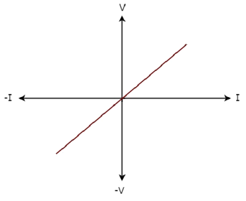
Step 1 − Verifying the network element as linear or non-linear.
From the above figure, the V-I characteristics of a network element is a straight line passing through the origin. Hence, it is a Linear element.
Step 2 − Verifying the network element as active or passive.
The given V-I characteristics of a network element lies in the first and third quadrants.
In the first quadrant, the values of both voltage (V) and current (I) are positive. So, the ratios of voltage (V) and current (I) gives positive impedance values.
Similarly, in the third quadrant, the values of both voltage (V) and current (I) have negative values. So, the ratios of voltage (V) and current (I) produce positive impedance values.
Since, the given V-I characteristics offer positive impedance values, the network element is a Passive element.
Step 3 − Verifying the network element as bilateral or unilateral.
For every point (I, V) on the characteristics, there exists a corresponding point (-I, -V) on the given characteristics. Hence, the network element is a Bilateral element.
Therefore, the given V-I characteristics show that the network element is a Linear, Passive, and Bilateral element.
Example 2
The V-I characteristics of a network element is shown below.
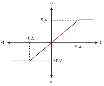
Step 1 − Verifying the network element as linear or non-linear.
From the above figure, the V-I characteristics of a network element is a straight line only between the points (-3A, -3V) and (5A, 5V). Beyond these points, the V-I characteristics are not following the linear relation. Hence, it is a Non-linear element.
Step 2 − Verifying the network element as active or passive.
The given V-I characteristics of a network element lies in the first and third quadrants. In these two quadrants, the ratios of voltage (V) and current (I) produce positive impedance values. Hence, the network element is a Passive element.
Step 3 − Verifying the network element as bilateral or unilateral.
Consider the point (5A, 5V) on the characteristics. The corresponding point (-5A, -3V) exists on the given characteristics instead of (-5A, -5V). Hence, the network element is a Unilateral element.
Therefore, the given V-I characteristics show that the network element is a Non-linear, Passive, and Unilateral element.
