- Microwave Engineering - Home
- Introduction
- Transmission Lines
- Modes of Propagation
- Types of Transmission Lines
- Waveguides
- Components
- Avalanche Transit Time Devices
- Microwave Devices
- E-Plane Tee
- H-Plane Tee
- E-H Plane Tee
- Rat-race Junction
- Directional Couplers
- Cavity Klystron
- Reflex Klystron
- Travelling Wave Tube
- Magnetrons
- Measurement Devices
- Measurements
- Example Problems
- Microwave Engineering -Quick Guide
- Microwave Engineering - Resources
- Microwave Engineering - Discussion
Microwave Engineering - Waveguides
Generally, if the frequency of a signal or a particular band of signals is high, the bandwidth utilization is high as the signal provides more space for other signals to get accumulated. However, high frequency signals can't travel longer distances without getting attenuated. We have studied that transmission lines help the signals to travel longer distances.
Microwaves propagate through microwave circuits, components and devices, which act as a part of Microwave transmission lines, broadly called as Waveguides.
A hollow metallic tube of uniform cross-section for transmitting electromagnetic waves by successive reflections from the inner walls of the tube is called as a Waveguide.
The following figure shows an example of a waveguide.
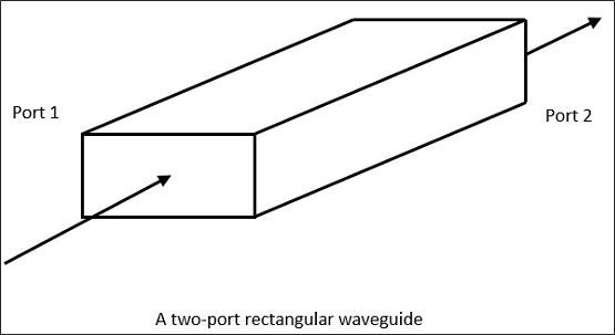
A waveguide is generally preferred in microwave communications. Waveguide is a special form of transmission line, which is a hollow metal tube. Unlike a transmission line, a waveguide has no center conductor.
The main characteristics of a Waveguide are −
The tube wall provides distributed inductance.
The empty space between the tube walls provide distributed capacitance.
These are bulky and expensive.
Advantages of Waveguides
Following are few advantages of Waveguides.
Waveguides are easy to manufacture.
They can handle very large power (in kilo watts).
Power loss is very negligible in waveguides.
They offer very low loss (low value of alpha-attenuation).
When microwave energy travels through waveguide, it experiences lower losses than a coaxial cable.
Types of Waveguides
There are five types of waveguides.
- Rectangular waveguide
- Circular waveguide
- Elliptical waveguide
- Single-ridged waveguide
- Double-ridged waveguide
The following figures show the types of waveguides.
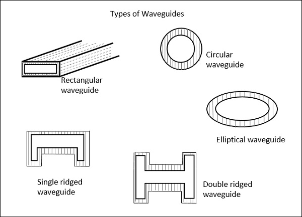
The types of waveguides shown above are hollow in the center and made up of copper walls. These have a thin lining of Au or Ag on the inner surface.
Let us now compare the transmission lines and waveguides.
Transmission Lines Vs Waveguides
The main difference between a transmission line and a wave guide is −
A two conductor structure that can support a TEM wave is a transmission line.
A one conductor structure that can support a TE wave or a TM wave but not a TEM wave is called as a waveguide.
The following table brings out the differences between transmission lines and waveguides.
| Transmission Lines | Waveguides |
|---|---|
| Supports TEM wave | Cannot support TEM wave |
| All frequencies can pass through | Only the frequencies that are greater than cut-off frequency can pass through |
| Two conductor transmission | One conductor transmission |
| Reflections are less | A wave travels through reflections from the walls of the waveguide |
| It has a characteristic impedance | It has wave impedance |
| Propagation of waves is according to "Circuit theory" | Propagation of waves is according to "Field theory" |
| It has a return conductor to earth | Return conductor is not required as the body of the waveguide acts as earth |
| Bandwidth is not limited | Bandwidth is limited |
| Waves do not disperse | Waves get dispersed |
Phase Velocity
Phase Velocity is the rate at which the wave changes its phase in order to undergo a phase shift of 2π radians. It can be understood as the change in velocity of the wave components of a sine wave, when modulated.
Let us derive an equation for the Phase velocity.
According to the definition, the rate of phase change at 2π radians is to be considered.
Which means, $λ$ / $T$ hence,
$$V = \frac{\lambda }{T}$$
Where,
$λ$ = wavelength and $T$ = time
$$V = \frac{\lambda }{T} = \lambda f$$
Since $f = \frac{1}{T}$
If we multiply the numerator and denominator by 2π then, we have
$$V = \lambda f = \frac{2\pi \lambda f}{2\pi }$$
We know that $\omega = 2\pi f$ and $\beta = \frac{2\pi }{f}$
The above equation can be written as,
$$V = \frac{2\pi f}{\frac{2\pi }{\lambda }} = \frac{\omega }{\beta }$$
Hence, the equation for Phase velocity is represented as
$$V_p = \frac{\omega }{\beta }$$
Group Velocity
Group Velocity can be defined as the rate at which the wave propagates through the waveguide. This can be understood as the rate at which a modulated envelope travels compared to the carrier alone. This modulated wave travels through the waveguide.
The equation of Group Velocity is represented as
$$V_g = \frac{d\omega }{d\beta }$$
The velocity of modulated envelope is usually slower than the carrier signal.
