- Microwave Engineering - Home
- Introduction
- Transmission Lines
- Modes of Propagation
- Types of Transmission Lines
- Waveguides
- Components
- Avalanche Transit Time Devices
- Microwave Devices
- E-Plane Tee
- H-Plane Tee
- E-H Plane Tee
- Rat-race Junction
- Directional Couplers
- Cavity Klystron
- Reflex Klystron
- Travelling Wave Tube
- Magnetrons
- Measurement Devices
- Measurements
- Example Problems
- Microwave Engineering -Quick Guide
- Microwave Engineering - Resources
- Microwave Engineering - Discussion
Microwave Engineering - Magnetrons
Unlike the tubes discussed so far, Magnetrons are the cross-field tubes in which the electric and magnetic fields cross, i.e. run perpendicular to each other. In TWT, it was observed that electrons when made to interact with RF, for a longer time, than in Klystron, resulted in higher efficiency. The same technique is followed in Magnetrons.
Types of Magnetrons
There are three main types of Magnetrons.
Negative Resistance Type
- The negative resistance between two anode segments, is used.
- They have low efficiency.
- They are used at low frequencies (< 500 MHz).
Cyclotron Frequency Magnetrons
The synchronism between the electric component and oscillating electrons is considered.
Useful for frequencies higher than 100MHz.
Travelling Wave or Cavity Type
The interaction between electrons and rotating EM field is taken into account.
High peak power oscillations are provided.
Useful in radar applications.
Cavity Magnetron
The Magnetron is called as Cavity Magnetron because the anode is made into resonant cavities and a permanent magnet is used to produce a strong magnetic field, where the action of both of these make the device work.
Construction of Cavity Magnetron
A thick cylindrical cathode is present at the center and a cylindrical block of copper, is fixed axially, which acts as an anode. This anode block is made of a number of slots that acts as resonant anode cavities.
The space present between the anode and cathode is called as Interaction space. The electric field is present radially while the magnetic field is present axially in the cavity magnetron. This magnetic field is produced by a permanent magnet, which is placed such that the magnetic lines are parallel to cathode and perpendicular to the electric field present between the anode and the cathode.
The following figures show the constructional details of a cavity magnetron and the magnetic lines of flux present, axially.
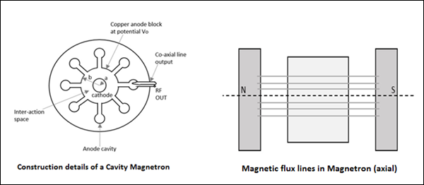
This Cavity Magnetron has 8 cavities tightly coupled to each other. An N-cavity magnetron has $N$ modes of operations. These operations depend upon the frequency and the phase of oscillations. The total phase shift around the ring of this cavity resonators should be $2n\pi$ where $n$ is an integer.
If $\phi_v$ represents the relative phase change of the AC electric field across adjacent cavities, then
$$\phi_v = \frac{2 \pi n}{N}$$
Where $n = 0, \: \pm1,\: \pm2,\: \pm \: (\frac{N}{2} -1), \: \pm \frac{N}{2}$
Which means that $\frac{N}{2}$ mode of resonance can exist if $N$ is an even number.
If,
$$n = \frac{N}{2} \quad then \quad \phi_v = \pi$$
This mode of resonance is called as $\pi-mode$.
$$n = 0 \quad then \quad \phi_v = 0$$
This is called as the Zero mode, because there will be no RF electric field between the anode and the cathode. This is also called as Fringing Field and this mode is not used in magnetrons.
Operation of Cavity Magnetron
When the Cavity Klystron is under operation, we have different cases to consider. Let us go through them in detail.
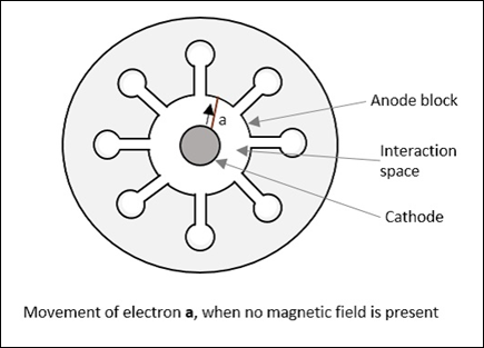
Case 1
If the magnetic field is absent, i.e. B = 0, then the behavior of electrons can be observed in the following figure. Considering an example, where electron a directly goes to anode under radial electric force.
Case 2
If there is an increase in the magnetic field, a lateral force acts on the electrons. This can be observed in the following figure, considering electron b which takes a curved path, while both forces are acting on it.
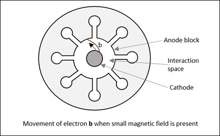
Radius of this path is calculated as
$$R = \frac{mv}{eB}$$
It varies proportionally with the velocity of the electron and it is inversely proportional to the magnetic field strength.
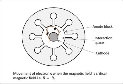
Case 3
If the magnetic field B is further increased, the electron follows a path such as the electron c, just grazing the anode surface and making the anode current zero. This is called as "Critical magnetic field" $(B_c)$, which is the cut-off magnetic field. Refer the following figure for better understanding.
Case 4
If the magnetic field is made greater than the critical field,
$$B > B_c$$
Then the electrons follow a path as electron d, where the electron jumps back to the cathode, without going to the anode. This causes "back heating" of the cathode. Refer the following figure.
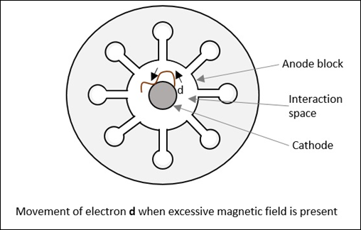
This is achieved by cutting off the electric supply once the oscillation begins. If this is continued, the emitting efficiency of the cathode gets affected.
Operation of Cavity Magnetron with Active RF Field
We have discussed so far the operation of cavity magnetron where the RF field is absent in the cavities of the magnetron (static case). Let us now discuss its operation when we have an active RF field.
As in TWT, let us assume that initial RF oscillations are present, due to some noise transient. The oscillations are sustained by the operation of the device. There are three kinds of electrons emitted in this process, whose actions are understood as electrons a, b and c, in three different cases.
Case 1
When oscillations are present, an electron a, slows down transferring energy to oscillate. Such electrons that transfer their energy to the oscillations are called as favored electrons. These electrons are responsible for bunching effect.
Case 2
In this case, another electron, say b, takes energy from the oscillations and increases its velocity. As and when this is done,
- It bends more sharply.
- It spends little time in interaction space.
- It returns to the cathode.
These electrons are called as unfavored electrons. They don't participate in the bunching effect. Also, these electrons are harmful as they cause "back heating".
Case 3
In this case, electron c, which is emitted a little later, moves faster. It tries to catch up with electron a. The next emitted electron d, tries to step with a. As a result, the favored electrons a, c and d form electron bunches or electron clouds. It called as "Phase focusing effect".
This whole process is understood better by taking a look at the following figure.
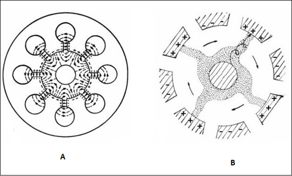
Figure A shows the electron movements in different cases while figure B shows the electron clouds formed. These electron clouds occur while the device is in operation. The charges present on the internal surface of these anode segments, follow the oscillations in the cavities. This creates an electric field rotating clockwise, which can be actually seen while performing a practical experiment.
While the electric field is rotating, the magnetic flux lines are formed in parallel to the cathode, under whose combined effect, the electron bunches are formed with four spokes, directed in regular intervals, to the nearest positive anode segment, in spiral trajectories.
