- Microwave Engineering - Home
- Introduction
- Transmission Lines
- Modes of Propagation
- Types of Transmission Lines
- Waveguides
- Components
- Avalanche Transit Time Devices
- Microwave Devices
- E-Plane Tee
- H-Plane Tee
- E-H Plane Tee
- Rat-race Junction
- Directional Couplers
- Cavity Klystron
- Reflex Klystron
- Travelling Wave Tube
- Magnetrons
- Measurement Devices
- Measurements
- Example Problems
- Microwave Engineering -Quick Guide
- Microwave Engineering - Resources
- Microwave Engineering - Discussion
Microwave Engineering - Microwave Devices
Just like other systems, the Microwave systems consists of many Microwave components, mainly with source at one end and load at the other, which are all connected with waveguides or coaxial cable or transmission line systems.
Following are the properties of waveguides.
- High SNR
- Low attenuation
- Lower insertion loss
Waveguide Microwave Functions
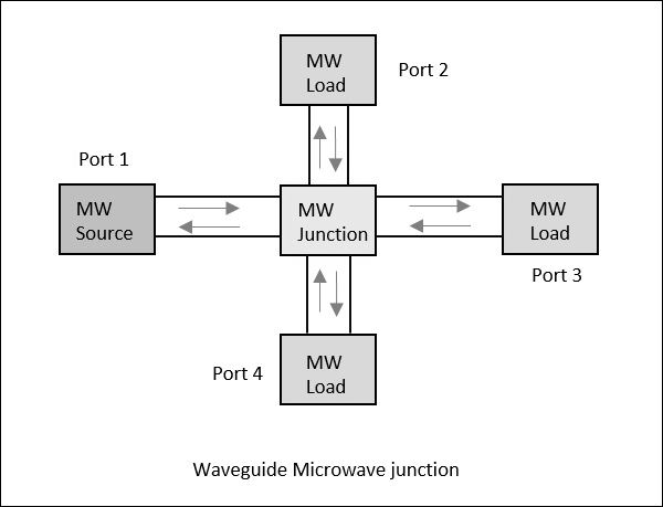
Consider a waveguide having 4 ports. If the power is applied to one port, it goes through all the 3 ports in some proportions where some of it might reflect back from the same port. This concept is clearly depicted in the following figure.
Scattering Parameters
For a two-port network, as shown in the following figure, if the power is applied at one port, as we just discussed, most of the power escapes from the other port, while some of it reflects back to the same port. In the following figure, if V1 or V2 is applied, then I1 or I2 current flows respectively.
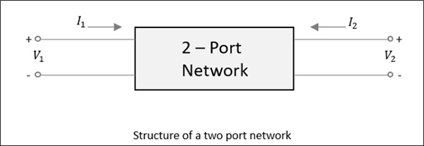
If the source is applied to the opposite port, another two combinations are to be considered. So, for a two-port network, 2 × 2 = 4 combinations are likely to occur.
The travelling waves with associated powers when scatter out through the ports, the Microwave junction can be defined by S-Parameters or Scattering Parameters, which are represented in a matrix form, called as "Scattering Matrix".
Scattering Matrix
It is a square matrix which gives all the combinations of power relationships between the various input and output ports of a Microwave junction. The elements of this matrix are called "Scattering Coefficients" or "Scattering (S) Parameters".
Consider the following figure.
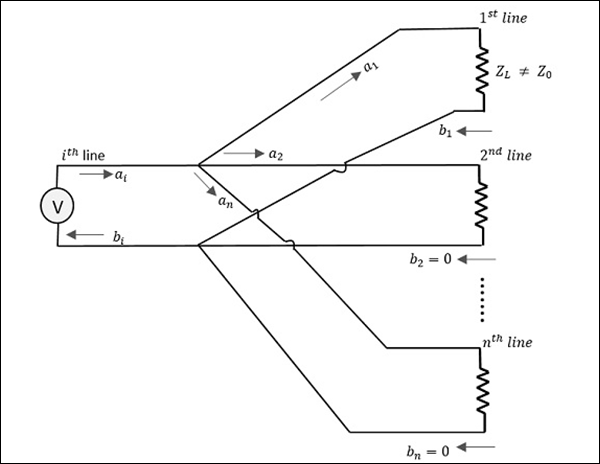
Here, the source is connected through $i^{th}$ line while $a_1$ is the incident wave and $b_1$ is the reflected wave.
If a relation is given between $b_1$ and $a_1$,
$$b_1 = (reflection \: \: coefficient)a_1 = S_{1i}a_1$$
Where
$S_{1i}$ = Reflection coefficient of $1^{st}$ line (where $i$ is the input port and $1$ is the output port)
$1$ = Reflection from $1^{st}$ line
$i$ = Source connected at $i^{th}$ line
If the impedance matches, then the power gets transferred to the load. Unlikely, if the load impedance doesn't match with the characteristic impedance. Then, the reflection occurs. That means, reflection occurs if
$$Z_l \neq Z_o$$
However, if this mismatch is there for more than one port, example $'n'$ ports, then $i = 1$ to $n$ (since $i$ can be any line from $1$ to $n$).
Therefore, we have
$$b_1 = S_{11}a_1 + S_{12}a_2 + S_{13}a_3 + ............... + S_{1n}a_n$$
$$b_2 = S_{21}a_1 + S_{22}a_2 + S_{23}a_3 + ............... + S_{2n}a_n$$
$$.$$
$$.$$
$$.$$
$$.$$
$$.$$
$$b_n = S_{n1}a_1 + S_{n2}a_2 + S_{n3}a_3 + ............... + S_{nn}a_n$$
When this whole thing is kept in a matrix form,
$$\begin{bmatrix} b_1\\ b_2\\ b_3\\ .\\ .\\ .\\ b_n \end{bmatrix} = \begin{bmatrix} S_{11}& S_{12}& S_{13}& ...& S_{1n}\\ S_{21}& S_{22}& S_{23}& ...& S_{2n}\\ .& .& .& ...& . \\ .& .& .& ...& . \\ .& .& .& ...& . \\ S_{n1}& S_{n2}& S_{n3}& ...& S_{nn}\\ \end{bmatrix} \times \begin{bmatrix} a_1\\ a_2\\ a_3\\ .\\ .\\ .\\ a_n \end{bmatrix}$$
Column matrix $[b]$ Scattering matrix $[S]$Matrix $[a]$
The column matrix $\left [ b \right ]$ corresponds to the reflected waves or the output, while the matrix $\left [ a \right ]$ corresponds to the incident waves or the input. The scattering column matrix $\left [ s \right ]$ which is of the order of $n \times n$ contains the reflection coefficients and transmission coefficients. Therefore,
$$\left [ b \right ] = \left [ S \right ]\left [ a \right ]$$
Properties of [S] Matrix
The scattering matrix is indicated as $[S]$ matrix. There are few standard properties for $[S]$ matrix. They are −
-
$[S]$ is always a square matrix of order (nxn)
$[S]_{n \times n}$
-
$[S]$ is a symmetric matrix
i.e., $S_{ij} = S_{ji}$
-
$[S]$ is a unitary matrix
i.e., $[S][S]^* = I$
The sum of the products of each term of any row or column multiplied by the complex conjugate of the corresponding terms of any other row or column is zero. i.e.,
$$\sum_{i=j}^{n} S_{ik} S_{ik}^{*} = 0 \: for \: k \neq j$$
$$( k = 1,2,3, ... \: n ) \: and \: (j = 1,2,3, ... \: n)$$
-
If the electrical distance between some $k^{th}$ port and the junction is $\beta _kI_k$, then the coefficients of $S_{ij}$ involving $k$, will be multiplied by the factor $e^{-j\beta kIk}$
In the next few chapters, we will take a look at different types of Microwave Tee junctions.
