- Microwave Engineering - Home
- Introduction
- Transmission Lines
- Modes of Propagation
- Types of Transmission Lines
- Waveguides
- Components
- Avalanche Transit Time Devices
- Microwave Devices
- E-Plane Tee
- H-Plane Tee
- E-H Plane Tee
- Rat-race Junction
- Directional Couplers
- Cavity Klystron
- Reflex Klystron
- Travelling Wave Tube
- Magnetrons
- Measurement Devices
- Measurements
- Example Problems
- Microwave Engineering -Quick Guide
- Microwave Engineering - Resources
- Microwave Engineering - Discussion
Measurement Devices
Among the Microwave measurement devices, a setup of Microwave bench, which consists of Microwave devices has a prominent place. This whole setup, with few alternations, is able to measure many values like guide wavelength, free space wavelength, cut-off wavelength, impedance, frequency, VSWR, Klystron characteristics, Gunn diode characteristics, power measurements, etc.
The output produced by microwaves, in determining power is generally of a little value. They vary with the position in a transmission line. There should be an equipment to measure the Microwave power, which in general will be a Microwave bench setup.
Microwave Bench General Measurement Setup
This setup is a combination of different parts which can be observed in detail. The following figure clearly explains the setup.
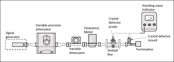
Signal Generator
As the name implies, it generates a microwave signal, in the order of a few milliwatts. This uses velocity modulation technique to transfer continuous wave beam into milliwatt power.
A Gunn diode oscillator or a Reflex Klystron tube could be an example for this microwave signal generator.
Precision Attenuator
This is the attenuator which selects the desired frequency and confines the output around 0 to 50db. This is variable and can be adjusted according to the requirement.
Variable Attenuator
This attenuator sets the amount of attenuation. It can be understood as a fine adjustment of values, where the readings are checked against the values of Precision Attenuator.
Isolator
This removes the signal that is not required to reach the detector mount. Isolator allows the signal to pass through the waveguide only in one direction.
Frequency Meter
This is the device which measures the frequency of the signal. With this frequency meter, the signal can be adjusted to its resonance frequency. It also gives provision to couple the signal to waveguide.
Crystal Detector
A crystal detector probe and crystal detector mount are indicated in the above figure, where the detector is connected through a probe to the mount. This is used to demodulate the signals.
Standing Wave Indicator
The standing wave voltmeter provides the reading of standing wave ratio in dB. The waveguide is slotted by some gap to adjust the clock cycles of the signal. Signals transmitted by waveguide are forwarded through BNC cable to VSWR or CRO to measure its characteristics.
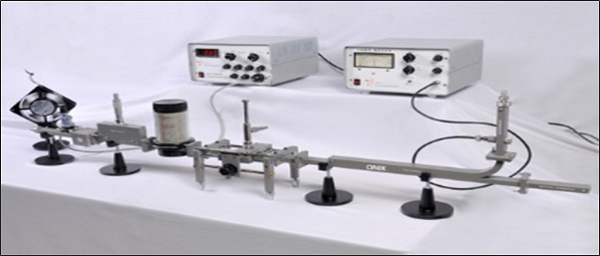
A microwave bench set up in real-time application would look as follows −
Now, let us take a look at the important part of this microwave bench, the slotted line.
Slotted Line
In a microwave transmission line or waveguide, the electromagnetic field is considered as the sum of incident wave from the generator and the reflected wave to the generator. The reflections indicate a mismatch or a discontinuity. The magnitude and phase of the reflected wave depends upon the amplitude and phase of the reflecting impedance.
The standing waves obtained are measured to know the transmission line imperfections which is necessary to have a knowledge on impedance mismatch for effective transmission. This slotted line helps in measuring the standing wave ratio of a microwave device.
Construction
The slotted line consists of a slotted section of a transmission line, where the measurement has to be done. It has a travelling probe carriage, to let the probe get connected wherever necessary, and the facility for attaching and detecting the instrument.
In a waveguide, a slot is made at the center of the broad side, axially. A movable probe connected to a crystal detector is inserted into the slot of the waveguide.
Operation
The output of the crystal detector is proportional to the square of the input voltage applied. The movable probe permits convenient and accurate measurement at its position. But, as the probe is moved along, its output is proportional to the standing wave pattern, which is formed inside the waveguide. A variable attenuator is employed here to obtain accurate results.
The output VSWR can be obtained by
$$VSWR = \sqrt{\frac{V_{max}}{V_{min}}}$$
Where, $V$ is the output voltage.
The following figure shows the different parts of a slotted line labelled.
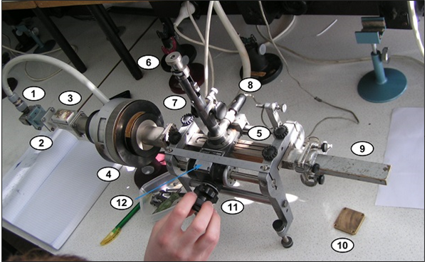
The parts labelled in the above figure indicate the following.
- Launcher − Invites the signal.
- Smaller section of the waveguide.
- Isolator − Prevents reflections to the source.
- Rotary variable attenuator − For fine adjustments.
- Slotted section − To measure the signal.
- Probe depth adjustment.
- Tuning adjustments − To obtain accuracy.
- Crystal detector − Detects the signal.
- Matched load − Absorbs the power exited.
- Short circuit − Provision to get replaced by a load.
- Rotary knob − To adjust while measuring.
- Vernier gauge − For accurate results.
In order to obtain a low frequency modulated signal on an oscilloscope, a slotted line with a tunable detector is employed. A slotted line carriage with a tunable detector can be used to measure the following.
- VSWR (Voltage Standing Wave Ratio)
- Standing wave pattern
- Impedance
- Reflection coefficient
- Return loss
- Frequency of the generator used
Tunable Detector
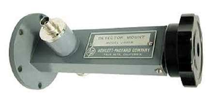
The tunable detector is a detector mount which is used to detect the low frequency square wave modulated microwave signals. The following figure gives an idea of a tunable detector mount.

The following image represents the practical application of this device. It is terminated at the end and has an opening at the other end just as the above one.
To provide a match between the Microwave transmission system and the detector mount, a tunable stub is often used. There are three different types of tunable stubs.
- Tunable waveguide detector
- Tunable co-axial detector
- Tunable probe detector
Also, there are fixed stubs like −
- Fixed broad band tuned probe
- Fixed waveguide matched detector mount
The detector mount is the final stage on a Microwave bench which is terminated at the end.
