- Microwave Engineering - Home
- Introduction
- Transmission Lines
- Modes of Propagation
- Types of Transmission Lines
- Waveguides
- Components
- Avalanche Transit Time Devices
- Microwave Devices
- E-Plane Tee
- H-Plane Tee
- E-H Plane Tee
- Rat-race Junction
- Directional Couplers
- Cavity Klystron
- Reflex Klystron
- Travelling Wave Tube
- Magnetrons
- Measurement Devices
- Measurements
- Example Problems
- Microwave Engineering -Quick Guide
- Microwave Engineering - Resources
- Microwave Engineering - Discussion
Microwave Engineering - Transmission Lines
A transmission line is a connector which transmits energy from one point to another. The study of transmission line theory is helpful in the effective usage of power and equipment.
There are basically four types of transmission lines −
- Two-wire parallel transmission lines
- Coaxial lines
- Strip type substrate transmission lines
- Waveguides
While transmitting or while receiving, the energy transfer has to be done effectively, without the wastage of power. To achieve this, there are certain important parameters which has to be considered.
Main Parameters of a Transmission Line
The important parameters of a transmission line are resistance, inductance, capacitance and conductance.
Resistance and inductance together are called as transmission line impedance.
Capacitance and conductance together are called as admittance.
Resistance
The resistance offered by the material out of which the transmission lines are made, will be of considerable amount, especially for shorter lines. As the line current increases, the ohmic loss $\left ( I^{2}R \: loss \right )$ also increases.
The resistance $R$ of a conductor of length "$l$" and cross-section "$a$" is represented as
$$R = \rho \frac{l}{a}$$
Where
$\rho$ = resistivity of the conductor material, which is constant.
Temperature and the frequency of the current are the main factors that affect the resistance of a line. The resistance of a conductor varies linearly with the change in temperature. Whereas, if the frequency of the current increases, the current density towards the surface of the conductor also increases. Otherwise, the current density towards the center of the conductor increases.
This means, more the current flows towards the surface of the conductor, it flows less towards the center, which is known as the Skin Effect.
Inductance
In an AC transmission line, the current flows sinusoidally. This current induces a magnetic field perpendicular to the electric field, which also varies sinusoidally. This is well known as Faraday's law. The fields are depicted in the following figure.
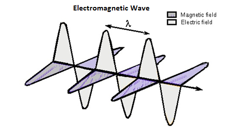
This varying magnetic field induces some EMF into the conductor. Now this induced voltage or EMF flows in the opposite direction to the current flowing initially. This EMF flowing in the opposite direction is equivalently shown by a parameter known as Inductance, which is the property to oppose the shift in the current.
It is denoted by "L". The unit of measurement is "Henry(H)".
Conductance
There will be a leakage current between the transmission line and the ground, and also between the phase conductors. This small amount of leakage current generally flows through the surface of the insulator. Inverse of this leakage current is termed as Conductance. It is denoted by "G".
The flow of line current is associated with inductance and the voltage difference between the two points is associated with capacitance. Inductance is associated with the magnetic field, while capacitance is associated with the electric field.
Capacitance
The voltage difference between the Phase conductors gives rise to an electric field between the conductors. The two conductors are just like parallel plates and the air in between them becomes dielectric. This pattern gives rise to the capacitance effect between the conductors.
Characteristic Impedance
If a uniform lossless transmission line is considered, for a wave travelling in one direction, the ratio of the amplitudes of voltage and current along that line, which has no reflections, is called as Characteristic impedance.
It is denoted by $Z_0$
$$Z_0 = \sqrt{\frac{voltage \:\: wave \:\: value}{current \:\: wave \:\: value}}$$
$$Z_0 = \sqrt{\frac{R + jwL}{G + jwC}}$$
For a lossless line, $R_0 = \sqrt{\frac{L}{C}}$
Where $L$ & $C$ are the inductance and capacitance per unit lengths.
Impedance Matching
To achieve maximum power transfer to the load, impedance matching has to be done. To achieve this impedance matching, the following conditions are to be met.
The resistance of the load should be equal to that of the source.
$$R_L = R_S$$
The reactance of the load should be equal to that of the source but opposite in sign.
$$X_L = -X_S$$
Which means, if the source is inductive, the load should be capacitive and vice versa.
Reflection Co-efficient
The parameter that expresses the amount of reflected energy due to impedance mismatch in a transmission line is called as Reflection coefficient. It is indicated by $\rho$ (rho).
It can be defined as "the ratio of reflected voltage to the incident voltage at the load terminals".
$$\rho = \frac{reflected\:voltage}{incident\:voltage} = \frac{V_r}{V_i} \: at \: load \: terminals$$
If the impedance between the device and the transmission line don't match with each other, then the energy gets reflected. The higher the energy gets reflected, the greater will be the value of $\rho$ reflection coefficient.
Voltage Standing Wave Ratio (VSWR)
The standing wave is formed when the incident wave gets reflected. The standing wave which is formed, contains some voltage. The magnitude of standing waves can be measured in terms of standing wave ratios.
The ratio of maximum voltage to the minimum voltage in a standing wave can be defined as Voltage Standing Wave Ratio (VSWR). It is denoted by "$S$".
$$S = \frac{\left |V_{max} \right |}{\left |V_{min} \right |} \quad 1\:\leq S \leq \infty$$
VSWR describes the voltage standing wave pattern that is present in the transmission line due to phase addition and subtraction of the incident and reflected waves.
Hence, it can also be written as
$$S = \frac{1 + \rho }{1 - \rho }$$
The larger the impedance mismatch, the higher will be the amplitude of the standing wave. Therefore, if the impedance is matched perfectly,
$$V_{max} : V_{min} = 1:1$$
Hence, the value for VSWR is unity, which means the transmission is perfect.
Efficiency of Transmission Lines
The efficiency of transmission lines is defined as the ratio of the output power to the input power.
$\% \: efficiency \: of \: transmission \: line \: \eta = \frac{Power \: delivered \: at \: reception}{Power \: sent \: from \: the \: transmission \: end} \times 100$
Voltage Regulation
Voltage regulation is defined as the change in the magnitude of the voltage between the sending and receiving ends of the transmission line.
$\% \: voltage \: regulation = \frac{sending \: end \: voltage - \: receiving \: end \: voltage}{sending \: end \: voltage} \times 100$
Losses due to Impedance Mismatch
The transmission line, if not terminated with a matched load, occurs in losses. These losses are many types such as attenuation loss, reflection loss, transmission loss, return loss, insertion loss, etc.
Attenuation Loss
The loss that occurs due to the absorption of the signal in the transmission line is termed as Attenuation loss, which is represented as
$$Attenuation \: loss (dB) = 10 \: log_{10} \left [ \frac{E_i - E_r}{E_t} \right ]$$
Where
$E_i$ = the input energy
$E_r$ = the reflected energy from the load to the input
$E_t$ = the transmitted energy to the load
Reflection Loss
The loss that occurs due to the reflection of the signal due to impedance mismatch of the transmission line is termed as Reflection loss, which is represented as
$$Reflection \: loss (dB) = 10 \: log_{10} \left [ \frac{E_i}{E_i - E_r} \right ]$$
Where
$E_i$ = the input energy
$E_r$ = the reflected energy from the load
Transmission Loss
The loss that occurs while transmission through the transmission line is termed as Transmission loss, which is represented as
$$Transmission \: loss(dB) = 10 \: log_{10} \: \frac{E_i}{E_t}$$
Where
$E_i$ = the input energy
$E_t$ = the transmitted energy
Return Loss
The measure of the power reflected by the transmission line is termed as Return loss, which is represented as
$$Return \: loss(dB) = 10 \: log_{10} \: \frac{E_i}{E_r}$$
Where
$E_i$ = the input energy
$E_r$ = the reflected energy
Insertion Loss
The loss that occurs due to the energy transfer using a transmission line compared to energy transfer without a transmission line is termed as Insertion loss, which is represented as
$$Insertion \: loss(dB) = 10 \: log_{10} \: \frac{E_1}{E_2}$$
Where
$E_1$ = the energy received by the load when directly connected to the source, without a transmission line.
$E_2$ = the energy received by the load when the transmission line is connected between the load and the source.
Stub Matching
If the load impedance mismatches the source impedance, a method called "Stub Matching" is sometimes used to achieve matching.
The process of connecting the sections of open or short circuit lines called stubs in the shunt with the main line at some point or points, can be termed as Stub Matching.
At higher microwave frequencies, basically two stub matching techniques are employed.
Single Stub Matching
In Single stub matching, a stub of certain fixed length is placed at some distance from the load. It is used only for a fixed frequency, because for any change in frequency, the location of the stub has to be changed, which is not done. This method is not suitable for coaxial lines.
Double Stub Matching
In double stud matching, two stubs of variable length are fixed at certain positions. As the load changes, only the lengths of the stubs are adjusted to achieve matching. This is widely used in laboratory practice as a single frequency matching device.
The following figures show how the stub matchings look.
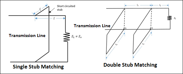
The single stub matching and double stub matching, as shown in the above figures, are done in the transmission lines to achieve impedance matching.
