- Microwave Engineering - Home
- Introduction
- Transmission Lines
- Modes of Propagation
- Types of Transmission Lines
- Waveguides
- Components
- Avalanche Transit Time Devices
- Microwave Devices
- E-Plane Tee
- H-Plane Tee
- E-H Plane Tee
- Rat-race Junction
- Directional Couplers
- Cavity Klystron
- Reflex Klystron
- Travelling Wave Tube
- Magnetrons
- Measurement Devices
- Measurements
- Example Problems
- Microwave Engineering -Quick Guide
- Microwave Engineering - Resources
- Microwave Engineering - Discussion
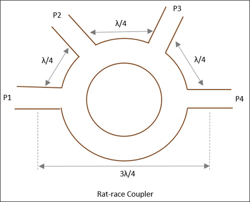
Microwave Engineering - Rat-race Junction
This microwave device is used when there is a need to combine two signals with no phase difference and to avoid the signals with a path difference.
A normal three-port Tee junction is taken and a fourth port is added to it, to make it a ratrace junction. All of these ports are connected in angular ring forms at equal intervals using series or parallel junctions.
The mean circumference of total race is 1.5λ and each of the four ports are separated by a distance of λ/4. The following figure shows the image of a Rat-race junction.
Let us consider a few cases to understand the operation of a Rat-race junction.
Case 1
If the input power is applied at port 1, it gets equally split into two ports, but in clockwise direction for port 2 and anti-clockwise direction for port 4. Port 3 has absolutely no output.
The reason being, at ports 2 and 4, the powers combine in phase, whereas at port 3, cancellation occurs due to λ/2 path difference.
Case 2
If the input power is applied at port 3, the power gets equally divided between port 2 and port 4. But there will be no output at port 1.
Case 3
If two unequal signals are applied at port 1 itself, then the output will be proportional to the sum of the two input signals, which is divided between port 2 and 4. Now at port 3, the differential output appears.
The Scattering Matrix for Rat-race junction is represented as
$$[S] = \begin{bmatrix} 0& S_{12}& 0& S_{14}\\ S_{21}& 0& S_{23}& 0\\ 0& S_{32}& 0& S_{34}\\ S_{41}& 0& S_{43}& 0 \end{bmatrix}$$
Applications
Rat-race junction is used for combining two signals and dividing a signal into two halves.
