- Microwave Engineering - Home
- Introduction
- Transmission Lines
- Modes of Propagation
- Types of Transmission Lines
- Waveguides
- Components
- Avalanche Transit Time Devices
- Microwave Devices
- E-Plane Tee
- H-Plane Tee
- E-H Plane Tee
- Rat-race Junction
- Directional Couplers
- Cavity Klystron
- Reflex Klystron
- Travelling Wave Tube
- Magnetrons
- Measurement Devices
- Measurements
- Example Problems
- Microwave Engineering -Quick Guide
- Microwave Engineering - Resources
- Microwave Engineering - Discussion
Microwave Engineering - E-H Plane Tee
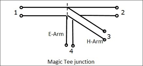
An E-H Plane Tee junction is formed by attaching two simple waveguides one parallel and the other series, to a rectangular waveguide which already has two ports. This is also called as Magic Tee, or Hybrid or 3dB coupler.
The arms of rectangular waveguides make two ports called collinear ports i.e., Port 1 and Port 2, while the Port 3 is called as H-Arm or Sum port or Parallel port. Port 4 is called as E-Arm or Difference port or Series port.
The cross-sectional details of Magic Tee can be understood by the following figure.
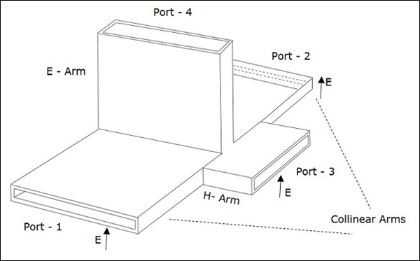
The following figure shows the connection made by the side arms to the bi-directional waveguide to form both parallel and serial ports.
Characteristics of E-H Plane Tee
If a signal of equal phase and magnitude is sent to port 1 and port 2, then the output at port 4 is zero and the output at port 3 will be the additive of both the ports 1 and 2.
If a signal is sent to port 4, (E-arm) then the power is divided between port 1 and 2 equally but in opposite phase, while there would be no output at port 3. Hence, $S_{34}$ = 0.
If a signal is fed at port 3, then the power is divided between port 1 and 2 equally, while there would be no output at port 4. Hence, $S_{43}$ = 0.
If a signal is fed at one of the collinear ports, then there appears no output at the other collinear port, as the E-arm produces a phase delay and the H-arm produces a phase advance. So, $S_{12}$ = $S_{21}$ = 0.
Properties of E-H Plane Tee
The properties of E-H Plane Tee can be defined by its $\left [ S \right ]_{4\times 4}$ matrix.
It is a 4×4 matrix as there are 4 possible inputs and 4 possible outputs.
$[S] = \begin{bmatrix} S_{11}& S_{12}& S_{13}& S_{14}\\ S_{21}& S_{22}& S_{23}& S_{24}\\ S_{31}& S_{32}& S_{33}& S_{34}\\ S_{41}& S_{42}& S_{43}& S_{44} \end{bmatrix}$ ........ Equation 1
As it has H-Plane Tee section
$S_{23} = S_{13}$........ Equation 2
As it has E-Plane Tee section
$S_{24} = -S_{14}$........ Equation 3
The E-Arm port and H-Arm port are so isolated that the other won't deliver an output, if an input is applied at one of them. Hence, this can be noted as
$S_{34} = S_{43} = 0$........ Equation 4
From the symmetry property, we have
$S_{ij} = S_{ji}$
$S_{12} = S_{21}, S_{13} = S_{31}, S_{14} = S_{41}$
$S_{23} = S_{32}, S_{24} = S_{42}, S_{34} = S_{43}$........ Equation 5
If the ports 3 and 4 are perfectly matched to the junction, then
$S_{33} = S_{44} = 0$........ Equation 6
Substituting all the above equations in equation 1, to obtain the $[S]$ matrix,
$[S] = \begin{bmatrix} S_{11}& S_{12}& S_{13}& S_{14}\\ S_{12}& S_{22}& S_{13}& -S_{14}\\ S_{13}& S_{13}& 0& 0\\ S_{14}& -S_{14}& 0& 0 \end{bmatrix}$........ Equation 7
From Unitary property, $[S][S]^\ast = [I]$
$\begin{bmatrix} S_{11}& S_{12}& S_{13}& S_{14}\\ S_{12}& S_{22}& S_{13}& -S_{14}\\ S_{13}& S_{13}& 0& 0\\ S_{14}& -S_{14}& 0& 0 \end{bmatrix} \begin{bmatrix} S_{11}^{*}& S_{12}^{*}& S_{13}^{*}& S_{14}^{*}\\ S_{12}^{*}& S_{22}^{*}& S_{13}^{*}& -S_{14}^{*}\\ S_{13}& S_{13}& 0& 0\\ S_{14}& -S_{14}& 0& 0 \end{bmatrix}$
$ = \begin{bmatrix} 1& 0& 0& 0\\ 0& 1& 0& 0\\ 0& 0& 1& 0\\ 0& 0& 0& 1 \end{bmatrix}$
$R_1C_1 : \left | S_{11} \right |^2 + \left | S_{12} \right |^2 + \left | S_{13} \right |^2 = 1 + \left | S_{14} \right |^2 = 1$ ......... Equation 8
$R_2C_2 : \left | S_{12} \right |^2 + \left | S_{22} \right |^2 + \left | S_{13} \right |^2 = 1 + \left | S_{14} \right |^2 = 1$ ......... Equation 9
$R_3C_3 : \left | S_{13} \right |^2 + \left | S_{13} \right |^2 = 1$ ......... Equation 10
$R_4C_4 : \left | S_{14} \right |^2 + \left | S_{14} \right |^2 = 1$ ......... Equation 11
From the equations 10 and 11, we get
$S_{13} = \frac{1}{\sqrt{2}}$........ Equation 12
$S_{14} = \frac{1}{\sqrt{2}}$........ Equation 13
Comparing the equations 8 and 9, we have
$S_{11} = S_{22}$ ......... Equation 14
Using these values from the equations 12 and 13, we get
$\left | S_{11} \right |^2 + \left | S_{12} \right |^2 + \frac{1}{2} + \frac{1}{2} = 1$
$\left | S_{11} \right |^2 + \left | S_{12} \right |^2 = 0$
$S_{11} = S_{22} = 0$ ......... Equation 15
From equation 9, we get $S_{22} = 0$ ......... Equation 16
Now we understand that ports 1 and 2 are perfectly matched to the junction. As this is a 4 port junction, whenever two ports are perfectly matched, the other two ports are also perfectly matched to the junction.
The junction where all the four ports are perfectly matched is called as Magic Tee Junction.
By substituting the equations from 12 to 16, in the $[S]$ matrix of equation 7, we obtain the scattering matrix of Magic Tee as
$$[S] = \begin{bmatrix} 0& 0& \frac{1}{2}& \frac{1}{\sqrt{2}}\\ 0& 0& \frac{1}{2}& -\frac{1}{\sqrt{2}}\\ \frac{1}{\sqrt{2}}& \frac{1}{\sqrt{2}}& 0& 0\\ \frac{1}{\sqrt{2}}& -\frac{1}{\sqrt{2}}& 0& 0 \end{bmatrix}$$
We already know that, $[b]$ = $[S] [a]$
Rewriting the above, we get
$$\begin{vmatrix} b_1\\ b_2\\ b_3\\ b_4 \end{vmatrix} = \begin{bmatrix} 0& 0& \frac{1}{2}& \frac{1}{\sqrt{2}}\\ 0& 0& \frac{1}{2}& -\frac{1}{\sqrt{2}}\\ \frac{1}{\sqrt{2}}& \frac{1}{\sqrt{2}}& 0& 0\\ \frac{1}{\sqrt{2}}& -\frac{1}{\sqrt{2}}& 0& 0 \end{bmatrix} \begin{vmatrix} a_1\\ a_2\\ a_3\\ a_4 \end{vmatrix}$$
Applications of E-H Plane Tee
Some of the most common applications of E-H Plane Tee are as follows −
E-H Plane junction is used to measure the impedance − A null detector is connected to E-Arm port while the Microwave source is connected to H-Arm port. The collinear ports together with these ports make a bridge and the impedance measurement is done by balancing the bridge.
E-H Plane Tee is used as a duplexer − A duplexer is a circuit which works as both the transmitter and the receiver, using a single antenna for both purposes. Port 1 and 2 are used as receiver and transmitter where they are isolated and hence will not interfere. Antenna is connected to E-Arm port. A matched load is connected to H-Arm port, which provides no reflections. Now, there exists transmission or reception without any problem.
E-H Plane Tee is used as a mixer − E-Arm port is connected with antenna and the H-Arm port is connected with local oscillator. Port 2 has a matched load which has no reflections and port 1 has the mixer circuit, which gets half of the signal power and half of the oscillator power to produce IF frequency.
In addition to the above applications, an E-H Plane Tee junction is also used as Microwave bridge, Microwave discriminator, etc.
