- Microwave Engineering - Home
- Introduction
- Transmission Lines
- Modes of Propagation
- Types of Transmission Lines
- Waveguides
- Components
- Avalanche Transit Time Devices
- Microwave Devices
- E-Plane Tee
- H-Plane Tee
- E-H Plane Tee
- Rat-race Junction
- Directional Couplers
- Cavity Klystron
- Reflex Klystron
- Travelling Wave Tube
- Magnetrons
- Measurement Devices
- Measurements
- Example Problems
- Microwave Engineering -Quick Guide
- Microwave Engineering - Resources
- Microwave Engineering - Discussion
Microwave Engineering - Directional Couplers
A Directional coupler is a device that samples a small amount of Microwave power for measurement purposes. The power measurements include incident power, reflected power, VSWR values, etc.
Directional Coupler is a 4-port waveguide junction consisting of a primary main waveguide and a secondary auxiliary waveguide. The following figure shows the image of a directional coupler.
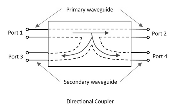
Directional coupler is used to couple the Microwave power which may be unidirectional or bi-directional.
Properties of Directional Couplers
The properties of an ideal directional coupler are as follows.
All the terminations are matched to the ports.
When the power travels from Port 1 to Port 2, some portion of it gets coupled to Port 4 but not to Port 3.
As it is also a bi-directional coupler, when the power travels from Port 2 to Port 1, some portion of it gets coupled to Port 3 but not to Port 4.
If the power is incident through Port 3, a portion of it is coupled to Port 2, but not to Port 1.
If the power is incident through Port 4, a portion of it is coupled to Port 1, but not to Port 2.
Port 1 and 3 are decoupled as are Port 2 and Port 4.
Ideally, the output of Port 3 should be zero. However, practically, a small amount of power called back power is observed at Port 3. The following figure indicates the power flow in a directional coupler.
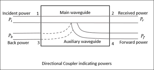
Where
$P_i$ = Incident power at Port 1
$P_r$ = Received power at Port 2
$P_f$ = Forward coupled power at Port 4
$P_b$ = Back power at Port 3
Following are the parameters used to define the performance of a directional coupler.
Coupling Factor (C)
The Coupling factor of a directional coupler is the ratio of incident power to the forward power, measured in dB.
$$C = 10 \: log_{10}\frac{P_i}{P_f}dB$$
Directivity (D)
The Directivity of a directional coupler is the ratio of forward power to the back power, measured in dB.
$$D = 10 \: log_{10}\frac{P_f}{P_b}dB$$
Isolation
It defines the directive properties of a directional coupler. It is the ratio of incident power to the back power, measured in dB.
$$I = 10 \: log_{10}\frac{P_i}{P_b}dB$$
Isolation in dB = Coupling factor + Directivity
Two-Hole Directional Coupler
This is a directional coupler with same main and auxiliary waveguides, but with two small holes that are common between them. These holes are ${\lambda_g}/{4}$ distance apart where λg is the guide wavelength. The following figure shows the image of a two-hole directional coupler.
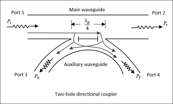
A two-hole directional coupler is designed to meet the ideal requirement of directional coupler, which is to avoid back power. Some of the power while travelling between Port 1 and Port 2, escapes through the holes 1 and 2.
The magnitude of the power depends upon the dimensions of the holes. This leakage power at both the holes are in phase at hole 2, adding up the power contributing to the forward power Pf. However, it is out of phase at hole 1, cancelling each other and preventing the back power to occur.
Hence, the directivity of a directional coupler improves.
Waveguide Joints
As a waveguide system cannot be built in a single piece always, sometimes it is necessary to join different waveguides. This joining must be carefully done to prevent problems such as − Reflection effects, creation of standing waves, and increasing the attenuation, etc.
The waveguide joints besides avoiding irregularities, should also take care of E and H field patterns by not affecting them. There are many types of waveguide joints such as bolted flange, flange joint, choke joint, etc.
