
Article Categories
- All Categories
-
 Data Structure
-
 Networking
-
 RDBMS
RDBMS
-
 Operating System
-
 Java
Java
-
 MS Excel
-
 iOS
iOS
-
 HTML
HTML
-
 CSS
CSS
-
 Android
-
 Python
-
 C Programming
-
 C++
C++
-
 C#
C#
-
 MongoDB
-
 MySQL
MySQL
-
 Javascript
-
 PHP
PHP
-
 Economics & Finance
How to interface Arduino with a GSM Module and read SMS?
In this article, we will see how to interface Arduino with a GSM Module, and read an SMS sent to the SIM card attached to the module.
You will need the following −
An Arduino board
A GSM Module (SIM800C, SIM900A, are popular examples, but you can have any other module as well)
A GSM (2G) SIM Card, or a 4G SIM Card with 2G fallback option (Jio SIM Cards won't work for this project)
A GSM Antenna
You could also get a GSM Module development board, like the one below (the SIM Card Holder is on the other side of the board) −
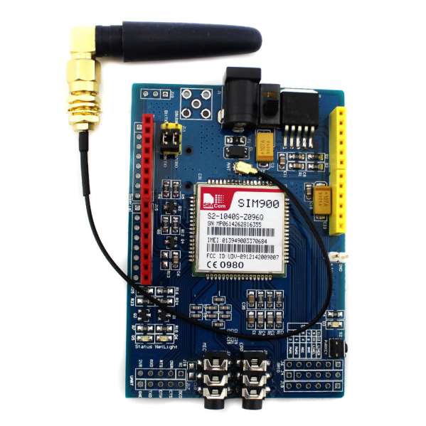
A GSM Module interacts with a microcontroller via UART (see the jumper holes for the UART at the bottom left of the above board). We will use SoftwareSerial to connect to the GSM Module.
Circuit Diagram
The circuit diagram is shown below −
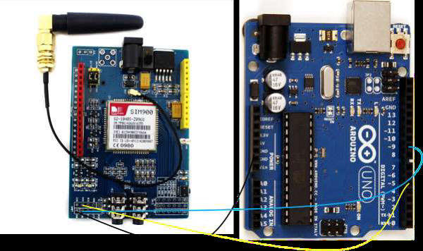
As you can see, we have connected the RX of the GSM Module to pin 5 of Arduino, the TX to pin 9 and GND to GND. Since the GSM Module will be powered using a separate 1A+ adapter, no need to connect Vcc to Arduino (it needs more current than what Arduino pins can provide). Since in UART connection, TX of one module is connected to RX of other and vice versa, pin5 of Arduino will serve as TX (because it is connected to RX of GSM), and pin 9 will serve as RX.
Now, GSM Modules work on AT Commands. Going into the details of the AT Commands is beyond the scope of this article. However, you should know that each GSM Command comes with its own AT Commands manual, which you should refer to for all operations (sending SMS, making calls, connecting to internet, etc.)
The AT Commands manual for SIM900 can be found here.
For reading a received SMS, two AT Commands will be used (one for setting the mode of the module to text mode, and the other for actually reading the SMS) −
AT+CMGF=1 − This sets the SMS format to text mode. The other mode is PDU (Protocol Data Unit) mode. We are interested in only text messages, so we will set the mode to text mode.
The second AT Command is AT+CMGL which is not the SMS read command, but rather, the SMS list command. I personally find it more convenient than SMS read command.
While AT+CMGR requires you to specify the memory location from where you want to read the SMS, AT+CMGL requires you to provide the type of SMS you want to read (stored, unread, etc.). It then fetches all the SMSes of that type and returns them as a list.
Syntax
Its syntax is −
AT+CMGL = <stat>[,<mode>]
As is indicated by the square brackets, the mode parameter is optional.
The
"REC UNREAD": Received unread messages
"REC READ": Received read messages
"STO UNSENT": Stored unsent messages
"STO SENT": Stored sent messages
"ALL": All messages
The
0: Normal mode (default)
1: Do not change status of specified SMS record (i.e., unread message remains unread even after it is fetched using this command)
The detailed return output of this command can be found in pages 102-104 of the AT Command Manual for this GSM Module.
The Arduino code incorporating the above AT Commands is given below. If you are using a board other than Arduino Uno, all digital pins may not support SoftwareSerial. Read the limitations of SoftwareSerial here.
#include <SoftwareSerial.h>
SoftwareSerial gsmSerial(9, 5); // RX, TX
void setup()
{
   gsmSerial.begin(9600); // Setting the baud rate of GSM Module
   Serial.begin(9600); // Setting the baud rate of Serial Monitor (Arduino)
   delay(1000);
   Serial.println("Preparing to read received SMSes");
}
void loop()
{
   ReadUnreadMessages();
   delay(1000);
}
void ReadUnreadMessages()
{
   Serial.println("Setting the GSM in text mode");
   gsmSerial.println("AT+CMGF=1\r");
   delay(2000);
   Serial.println("Fetching list of received unread SMSes!");
   gsmSerial.println("AT+CMGL="REC UNREAD"\r");
   delay(2000);
   // Print the response on the Serial Monitor
   while (gsmSerial.available() > 0) {
      Serial.write(gsmSerial.read());
   }
}
The relevant Serial Monitor output, when SMS has been received, will be similar to the following −
+CMGL: 1,"REC UNREAD","+911234567890",,"06/06/21,00:04:10+40"
SMS List Demo.
+CMGL: 2,"REC UNREAD","+911234567890",,"06/06/21,00:06:12+30"
SMS List Demo Again.
Note that you get the phone number from which the SMS was sent and the timestamp of the message as well, along with the actual SMS text. The blank field between the mobile number and the timestamp ideally contains the name or rather, the text associated with the phone number in the phone book.
You can write a simple function to parse the information you receive from the CMGL output.

3K+ Views
