
Article Categories
- All Categories
-
 Data Structure
-
 Networking
-
 RDBMS
RDBMS
-
 Operating System
-
 Java
Java
-
 MS Excel
-
 iOS
iOS
-
 HTML
HTML
-
 CSS
CSS
-
 Android
-
 Python
-
 C Programming
-
 C++
C++
-
 C#
C#
-
 MongoDB
-
 MySQL
MySQL
-
 Javascript
-
 PHP
PHP
-
 Economics & Finance
Send SMS using a GSM module connected to Arduino
In this article, we will see how to interface Arduino with a GSM Module, and send SMS using the module. You will need the following −
Arduino board
A GSM Module (SIM800C, SIM900A, are popular examples, but you can have any other module as well)
A GSM (2G) SIM Card, or a 4G SIM Card with 2G fallback option (Jio SIM Cards won’t work for this project)
GSM Antenna
You could also get a GSM Module development board, like the one below (the SIM Card Holder is on the other side of the board) −
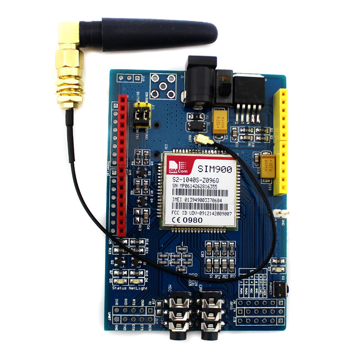
A GSM Module interacts with a microcontroller via UART (see the jumper holes for the UART at the bottom left of the above board). We will use SoftwareSerial to connect to the GSM Module. The circuit diagram is shown below −
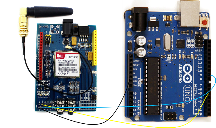
As you can see, we have connected the RX of the GSM Module to pin 5 of Arduino, the TX to pin 9 and GND to GND. Since the GSM Module will be powered using a separate 1A+ adapter,no need to connect Vcc to Arduino (it needs more current than what Arduino pins can provide). Since in UART connection, TX of one module is connected to RX of other and vice versa, pin 5 of Arduino will serve as TX (because it is connected to RX of GSM), and pin 9 will serve as RX.
Now, GSM Modules work on AT Commands. Going into the details of the AT Commands is beyond the scope of this article. However, you should know that each GSM Command comes with its own AT Commands manual, which you should refer to for all operations (sending SMS, making calls, connecting to internet, etc.)
The AT Commands manual for SIM900 can be found here.
For sending SMS, two AT Commands will be used −
AT+CMGF=1 - This sets the SMS format to text mode.
The other mode is PDU (Protocol Data Unit) mode.
You can read about the difference here.
We are interested in only text messages, so we will set the mode to text mode.
The second AT Command is AT+CMGS which is the SMS send command. Its syntax is −
AT+CMGS = "<phone_number_with_country_code>" <cr>
<SMS Text> ESC
The ESC character at the end is important as it indicates the end of the SMS text. The ESC character is Ctrl+Z which in hex translates to 0x1A (ASCII decimal equivalent is 26).
The Arduino code incorporating the above AT Commands is given below. If you are using a board other than Arduino Uno, all digital pins may not support SoftwareSerial. Read the limitations of SoftwareSerial here.
#include <SoftwareSerial.h>

SoftwareSerial gsmSerial(9, 5); //RX, TX

void setup()
{
   gsmSerial.begin(9600); // Setting the baud rate of GSM Module
   Serial.begin(9600);    // Setting the baud rate of Serial Monitor (Arduino)
   delay(1000);
   Serial.println("Preparing to send SMS");
   SendMessage();
}

void loop()
{

}
void SendMessage()
{
   Serial.println("Setting the GSM in text mode");
   gsmSerial.println("AT+CMGF=1\r");
   delay(2000);
   Serial.println("Sending SMS to the desired phone number!");
   gsmSerial.println("AT+CMGS="+xxxxxxxxxxx"\r");
   // Replace x with mobile number
   delay(2000);

   gsmSerial.println("Hello from SIM900");    // SMS Text
   delay(200);
   gsmSerial.println((char)26);               // ASCII code of CTRL+Z
   delay(2000);
}
As an exercise, you can try printing the response of AT+CMGS command on the Serial Monitor.

11K+ Views
