
Article Categories
- All Categories
-
 Data Structure
-
 Networking
-
 RDBMS
RDBMS
-
 Operating System
-
 Java
Java
-
 MS Excel
-
 iOS
iOS
-
 HTML
HTML
-
 CSS
CSS
-
 Android
-
 Python
-
 C Programming
-
 C++
C++
-
 C#
C#
-
 MongoDB
-
 MySQL
MySQL
-
 Javascript
-
 PHP
PHP
-
 Economics & Finance
How to interface Arduino with a GSM Module and ping to a website?
In this article, we will see how to interface Arduino with a GSM Module, and ping to a website.You will need the following −
An Arduino board
A GSM Module (SIM800C, SIM900A, are popular examples, but you can have any other module as well)
A GSM (2G) SIM Card, or a 4G SIM Card with 2G fallback option (Jio SIM Cards won't work for this project)
A GSM Antenna
You could also get a GSM Module development board, like the one below (the SIM Card Holder is on the other side of the board) −
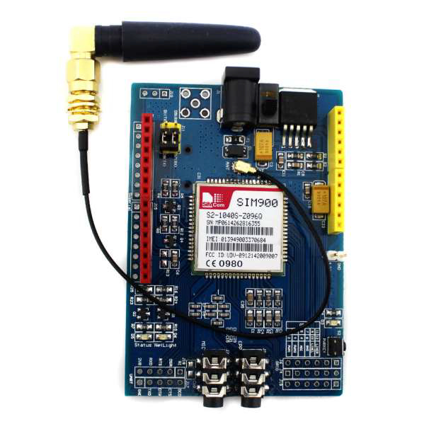
A GSM Module interacts with a microcontroller via UART (see the jumper holes for the UART at the bottom left of the above board). We will use SoftwareSerial to connect to the GSM Module. The circuit diagram is shown below −
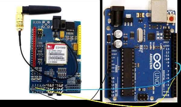
As you can see, we have connected the RX of the GSM Module to pin 5 of Arduino, the TX to pin 9 and GND to GND. Since the GSM Module will be powered using a separate 1A+ adapter, no need to connect Vcc to Arduino (it needs more current than what Arduino pins can provide).Since in UART connection, TX of one module is connected to RX of other and vice versa, pin 5 of Arduino will serve as TX (because it is connected to RX of GSM), and pin 9 will serve as RX.
Now, GSM Modules work on AT Commands. Going into the details of the AT Commands is beyond the scope of this article. However, you should know that each GSM Command comes with its own AT Commands manual, which you should refer to for all operations (sending SMS, making calls, connecting to internet, etc.)
The AT Commands manual for SIM900 can be found here.
However, the commands specific to ping are not present in the above AT Command Manual.For those commands, you will have to refer to the SIM900_PING_AT_Manual.
For pinging to a website, the main AT Command of interest is AT+CIPPING. Its syntax is −
AT+CIPPING = <IPAddr or Domain
Name>[,<retryNum>[,<dataLen>[,<timeout>[,<ttl>]]]]
As can be understood from the square brackets, all parameters apart from the first one are optional.
The description of the parameters is given below −
IPAddr or Domain Name − Either an IP Address in the "abc.xyz.lmn.pqr" format or a domain name like "www.google.com"
retryNum − The number of ping echo requests to send (default is 4, range is 1 to 100)
dataLen − The length of the ping echo request data (default is 32, range is 0 to 1024)
timeout − How long the module should wait for a single echo reply (in units of 100 ms) (default is 100, range is 1 to 600)
ttl − Time to live (default is 64, range is 1 to 255). It basically tells the network router if a packet has been in the network for too long. In the above case, we are telling that the packet should be discarded if it has been in the network for 64 hops or more.
In order to make CIPPING work, the GPRS context must be activated (AT+CGATT = 1). Mostly it is activated by default, but you may want to check (AT+CGATT), and set it to 1 manually if it is not set to 1.
The reply to each ping is in the following format −
+CIPPING: <replyId>, <IpAddress>, <replyTime>, <ttl>\r<br>
Where,
replyId is, as the name suggests, the ID or number of the reply
IpAddress is the IpAddress of the remote host sending the reply
replyTime is the time taken to receive the response (in units of 100 ms)
ttl, as we saw earlier, is the time to live.
If echo request timeout occurs, the response has replyTime value set to 600 and ttl set to 255.
Arduino Code
The Arduino code for executing the ping is shown below (we are pinging to google.com)
#include <SoftwareSerial.h>
SoftwareSerial gsmSerial(9, 5); // RX, TX
void setup()
{
   gsmSerial.begin(9600); // Setting the baud rate of GSM Module
   Serial.begin(9600); // Setting the baud rate of Serial Monitor (Arduino)
   delay(1000);
   Serial.println("Preparing to ping");
   Ping();
}
void loop()
{
}
void Ping()
{
   Serial.println("Attach to GPRS");
   gsmSerial.println("AT+CGATT=1\r");
   delay(2000);
   Serial.println("Setting the APN");
   gsmSerial.println("AT+CSTT="YourAPN"\r");
   delay(2000);
   Serial.println("Bringing up the wireless connection");
   gsmSerial.println("AT+CIICR\r");
   delay(8000);
   Serial.println("Getting local IP address");
   gsmSerial.println("AT+CIFSR\r");
   delay(5000);
   //Print the response on the Serial Monitor
   while (gsmSerial.available() > 0) {
   Serial.write(gsmSerial.read());
}
   Serial.println("Ping to Google");
   gsmSerial.println("AT+CIPPING="www.google.com"\r");
   delay(5000);
   //Print the response on the Serial Monitor
   while (gsmSerial.available() > 0) {
      Serial.write(gsmSerial.read());
   }
}
Replace YourAPN with the actual value of your APN ("www" works generally, but check with your network provider). On the Serial Monitor, you should first see the local IP address in response to AT+CIFSR. In response to AT+CIPPING, if all goes well, you may see a response like this:
+CIPPING: 1,"203.208.37.99",68,234
+CIPPING: 2,"203.208.37.99",75,232
+CIPPING: 3,"203.208.37.99",54,233
+CIPPING: 4,"203.208.37.99",66,236
Note the longer delays after AT+CIICR and AT+CIFSR and AT+CIPPING. This is done keeping in mind that bringing up wireless connection, and getting local IP and getting ping response can take some longer than usual time. You can try playing around with these values.
If, for some reason, your code isn't working as expected, you can refer to the application note for help.

2K+ Views
