
 Data Structure
 Networking
 RDBMS
RDBMS Operating System
 Java
Java MS Excel
 iOS
iOS HTML
HTML CSS
CSS Android
 Python
 C Programming
 C++
C++ C#
C# MongoDB
 MySQL
MySQL Javascript
 PHP
PHP
- Selected Reading
- UPSC IAS Exams Notes
- Developer's Best Practices
- Questions and Answers
- Effective Resume Writing
- HR Interview Questions
- Computer Glossary
- Who is Who
Interface Arduino with LoRa module
In this article we will see how to interface Arduino with the LoRa module E32. LoRa stands for Long Range. It uses license-free sub-GHz RF bands for operation. These bands are different in different countries. In India, the permissible band is 865-867 MHz. LoRa is very ideal for IoT applications thanks to its long range and low power consumption. However, the achievable data rates are limited (0.3 to 27 kbits/second). Longer the range, lower the data rate.
The E32 module that we will use looks like the one below. Depending on the frequency the module variant changes. For example, the one shown below is E32-TTL-100, which operates from 410-441 MHz. Similarly, the E32 module operating from 862 to 893 MHz is E32-868T30D. Similarly, there may be other variants for other frequencies.
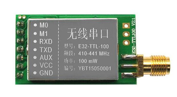
The E32 module works on UART (as you can see from the RX and TX pins on the module). It is based on SEMTECH's SX1276 RF chip. There are two configuration pins (M0 and M1),which together determine four operating modes.
You can find more detailed description of these modes in the user manual. In this tutorial, we will work with the Normal mode only, on both the receiver and the transmitter, i.e., we will set both M0 and M1 to 0.
Configuring the E32 module
Note that E32 module can be configured only in the following mode −
M0 and M1 are both set to 1 (HIGH)
Serial configuration is 8N1, with baud rate of 9600.
The parameter setting command of E32 is 6 bytes long. The bytes are −
Byte 0 − It can be either 0xC0 or 0xC2. C0 tells the module that the settings have to be preserved even after power down. C2 means that settings need not be remembered after power down.
Bytes 1 and 2 − These dictate the address of the module. Byte 1 is the higher byte of the address and byte 2 is the lower byte of the address. You can keep any values you wish. But keep distinct values for distinct modules.
Byte 3 − This byte dictates the data transfer parameters (both UART and air data transfer). The description of the individual bits can be obtained from the user manual.
Byte 4 − This byte dictates the operating frequency of LoRa. For different modules there are different default frequencies. For example, the module 868T30D has the default frequency of 868 MHz, but the frequency range is 862 to 893 MHz. To adjust the frequency to a number other than the default, you use this byte. Each module’s user manual tells you how to adjust this byte to get the desired frequency. The general rules are also mentioned in the global user manual.
Byte 5 − This byte contains various transmission related parameters, like mode (transparent or fixed), transmission power, etc. You can refer to the user manual for more details (the details are too large to reproduce here). However, this byte can be generally left to the default value (the default is 0x44 for most modules, but you can check your particular model’s user manual).
Circuit Diagram
The circuit diagram is shown below for one end (transmitter). The circuit will be exactly the same on the receiving side.
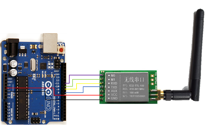
Note that you need to get an antenna for the frequency range of your LoRa module. In this example, we are using a 433 MHz module (E32-TTL-100). If you are using a module of a different frequency, you may want an antenna of that same frequency.
The connections between Arduino and LoRa module are quote straightforward. M0, M1, RXD and TXD are to be connected to 4 GPIOs (we have connected them to 11, 10, 9 and 8 respectively). Vcc is connected to 5V and GND to GND. Please note that on Arduino, pin 8 will be RX (since it is connected to TX of the LoRa module), and pin 9 will be TX.
Code Walkthrough
The code is given below (if you are using a board other than Arduino Uno, all digital pins may not support SoftwareSerial. Read the limitations of SoftwareSerial here) −
// (Send and Receive)
#include <SoftwareSerial.h>
SoftwareSerial loraSerial(8,9); //RX, TX

#define M0 11
#define M1 10

void setup() {
   Serial.begin(9600);
   pinMode(M0, OUTPUT);
   pinMode(M1, OUTPUT);

   //Set M0 and M1 to high for parameter setting
   digitalWrite(M0, HIGH);
   digitalWrite(M1, HIGH);

   loraSerial.begin(9600);
   while (loraSerial.available() && loraSerial.read());

   //Send configuration commands to the module
   uint8_t config_struct[6];
   config_struct[0] = 0xC0; //Store in internal flash
   config_struct[1] = 0x00; // Address High, set a different value on the receiving side
   config_struct[2] = 0x00; //Address Low
   config_struct[3] = 0x35; //8N1, 57600 Baud rate, 19.2 kbps Air data rate
   config_struct[4] = 0x17; //433 MHz
   config_struct[5] = 0x44; //Default Options

   loraSerial.write(config_struct,6);
   delay(2000);

   Serial.println("Config Complete");
   digitalWrite(M0, LOW);
   digitalWrite(M1, LOW);
   loraSerial.begin(57600);

}

void loop() {
   if(Serial.available() > 0){
      char input = Serial.read();
      loraSerial.print(input);
   }

   if(loraSerial.available() > 0){
      char input = loraSerial.read();
      Serial.print(input);
   }
}
As you can see, in the setup, we first set M0 and M1 to HIGH, because we want to configure the LoRa module. The config struct (or rather array) is constructed (please remember to set a different value of the address on the receiving side). The comments explain the meaning of each byte’s value. You can also refer to E32-TTL-100’s user manual for more clarification here. Once the parameters are set, the M0 and M1 pins are set to LOW (Normal mode), and the baud rate of LoRa is changed to 57600 (because that’s what is configured via the parameters).
Within the loop, we take Serial input from the user. Whatever the user sends gets transmitted over LoRa, and whatever is received over LoRa is printed over the Serial Monitor. Thus, if you give a Serial input to the Arduino, the same text should get printed on the Serial Monitor of the receiving side, and if they type something, it should be visible on your Serial Monitor.
Go ahead and explore different configurations of the LoRa module, and also different commands that you can send to the module.

2K+ Views
