
Article Categories
- All Categories
-
 Data Structure
-
 Networking
-
 RDBMS
RDBMS
-
 Operating System
-
 Java
Java
-
 MS Excel
-
 iOS
iOS
-
 HTML
HTML
-
 CSS
CSS
-
 Android
-
 Python
-
 C Programming
-
 C++
C++
-
 C#
C#
-
 MongoDB
-
 MySQL
MySQL
-
 Javascript
-
 PHP
PHP
-
 Economics & Finance
Interface Zigbee with Arduino
Zigbee is a wireless communication protocol targeted for battery powered devices (it has both low power and low cost). It generally operates in the 2.4GHz range (although there are geographic variations), and supports data ranges from 20 to 250 kbits/s.
The transmission distance though, is small compared to the likes of LoRa. It is 10 to 100 m, whereas LoRa can transmit over a few kilometers. Another thing to note is that Zigbee communication doesn’t work very well if there is no line of sight between transmitter and receiver.
Even minor obstacles have been observed to significantly degrade the communication. Keep these limitations in mind when using Zigbee. You may want to look out for other options if your application can’t meet these constraints.
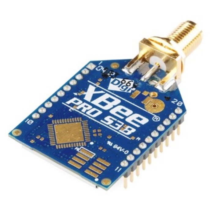
In order to make Zigbee work with Arduino, we will use the XBee module.
These work with UART and therefore, it is fairly easy to interface them with Arduino. It is important to look at the pinout of XBee though, to understand which are the UART pins −
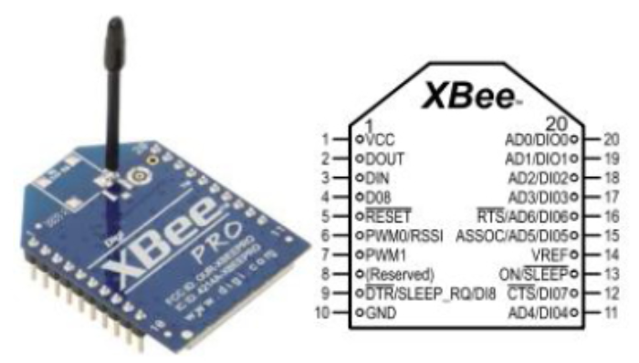
The DOUT and DIN pins in the figure above are the UART pins (TX and RX). They can be connected to two digital pins of Arduino (if you plan to use SoftwareSerial), or else to pins 0 and 1 of Arduino respectively (if you plan to use HW Serial). Please note that you won’t be able to read print statements from the Arduino on the Serial Monitor if you use Hardware Serial for Zigbee interface.
Configuring the XBee modules
The XBee modules (transmitter and receiver) need to be configured using the X-CTU Software. It can be downloaded from here. This software is provided by DigiKey, and they have given a detailed configuration guide. Therefore, there is no point of me reinventing the wheel here. You can find the guide here.
There’s another one by Sparkfun that is adapted to the newer version of the X-CTU software.
Here’s another brief one by Instructables.
Please note that the two XBee modules that intend to communicate with each other should belong to the same series.
Here are a few things to note about the configuration −
You will need a breakout board or an Explorer with a USB to UART converter for this configuration.
The PAN ID (Personal Area Network ID) has to be the same for the devices that want to communicate with each other.
One module needs to be set as the transmitter and the other as the receiver (this is determined by the CE field).
Note the baud rate that you set. This will be used in the Arduino code, when configuring the Serial communication with XBee.
Circuit Diagram −
Once your XBee is configured, you can connect it to the Arduino via the breakout/Explorer board. In that case, the pinout will be slightly different depending on which board/ Explorer you are using. Here we will assume you are connecting the XBee directly to Arduino Uno, in which case, the connections will be −
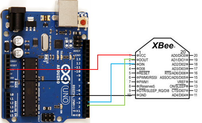
As you can see, we have connected Vcc to 3.3V on Arduino, GND to GND, DOUT (TX) to pin 2, which will act as RX on the Arduino, and DIN (RX) to pin 3, which will act as TX on the Arduino.
The connections will be similar on the receiving side as well. If you have an on-board antenna, that’s good, else you’ll have to connect an antenna to the UFL connector.
Code Walkthrough
The code is quite straightforward. If you are using a board other than Arduino Uno, all digital pins may not support SoftwareSerial. Read the limitations of SoftwareSerial here
On the transmitting side, the code will be −
#include <SoftwareSerial.h>
SoftwareSerial xbeeSerial(2,3); //RX, TX

void setup() {
   Serial.begin(9600);
   xbeeSerial.begin(9600);
}

void loop() {
   if(Serial.available() > 0){
      char input = Serial.read();
      xbeeSerial.print(input);
   }
}
As you can see, whatever is sent by the user on the Serial Monitor is sent to the XBee module,and it will be received on the receiving side. The code for the receiving side is −
#include <SoftwareSerial.h>
SoftwareSerial xbeeSerial(2,3); //RX, TX

void setup() {
   Serial.begin(9600);
   xbeeSerial.begin(9600);
}

void loop() {
   if(xbeeSerial.available() > 0){
      char input = xbeeSerial.read();
      Serial.print(input);
   }
}
Over here, whatever is received from XBee is forwarded to the Serial Monitor. Thus, when testing out the combined system, whatever you type on the Serial Monitor on the transmitter side should be printed on the Serial Monitor on the receiver side.

12K+ Views
