- Arduino - Home
- Arduino - Overview
- Arduino - Board Description
- Arduino - Installation
- Arduino - Program Structure
- Arduino - Data Types
- Arduino - Variables & Constants
- Arduino - Operators
- Arduino - Control Statements
- Arduino - Loops
- Arduino - Functions
- Arduino - Strings
- Arduino - String Object
- Arduino - Time
- Arduino - Arrays
- Arduino Function Libraries
- Arduino - I/O Functions
- Arduino - Advanced I/O Function
- Arduino - Character Functions
- Arduino - Math Library
- Arduino - Trigonometric Functions
- Arduino Advanced
- Arduino - Due & Zero
- Arduino - Pulse Width Modulation
- Arduino - Random Numbers
- Arduino - Interrupts
- Arduino - Communication
- Arduino - Inter Integrated Circuit
- Arduino - Serial Peripheral Interface
- Arduino Projects
- Arduino - Blinking LED
- Arduino - Fading LED
- Arduino - Reading Analog Voltage
- Arduino - LED Bar Graph
- Arduino - Keyboard Logout
- Arduino - Keyboard Message
- Arduino - Mouse Button Control
- Arduino - Keyboard Serial
- Arduino Sensors
- Arduino - Humidity Sensor
- Arduino - Temperature Sensor
- Arduino - Water Detector / Sensor
- Arduino - PIR Sensor
- Arduino - Ultrasonic Sensor
- Arduino - Connecting Switch
- Motor Control
- Arduino - DC Motor
- Arduino - Servo Motor
- Arduino - Stepper Motor
- Arduino And Sound
- Arduino - Tone Library
- Arduino - Wireless Communication
- Arduino - Network Communication
Arduino - Quick Guide
Arduino - Overview
Arduino is a prototype platform (open-source) based on an easy-to-use hardware and software. It consists of a circuit board, which can be programed (referred to as a microcontroller) and a ready-made software called Arduino IDE (Integrated Development Environment), which is used to write and upload the computer code to the physical board.
The key features are −
Arduino boards are able to read analog or digital input signals from different sensors and turn it into an output such as activating a motor, turning LED on/off, connect to the cloud and many other actions.
You can control your board functions by sending a set of instructions to the microcontroller on the board via Arduino IDE (referred to as uploading software).
Unlike most previous programmable circuit boards, Arduino does not need an extra piece of hardware (called a programmer) in order to load a new code onto the board. You can simply use a USB cable.
Additionally, the Arduino IDE uses a simplified version of C++, making it easier to learn to program.
Finally, Arduino provides a standard form factor that breaks the functions of the micro-controller into a more accessible package.
Board Types
Various kinds of Arduino boards are available depending on different microcontrollers used. However, all Arduino boards have one thing in common: they are programed through the Arduino IDE.
The differences are based on the number of inputs and outputs (the number of sensors, LEDs, and buttons you can use on a single board), speed, operating voltage, form factor etc. Some boards are designed to be embedded and have no programming interface (hardware), which you would need to buy separately. Some can run directly from a 3.7V battery, others need at least 5V.
Here is a list of different Arduino boards available.
Arduino boards based on ATMEGA328 microcontroller
| Board Name | Operating Volt | Clock Speed | Digital i/o | Analog Inputs | PWM | UART | Programming Interface |
|---|---|---|---|---|---|---|---|
| Arduino Uno R3 | 5V | 16MHz | 14 | 6 | 6 | 1 | USB via ATMega16U2 |
| Arduino Uno R3 SMD | 5V | 16MHz | 14 | 6 | 6 | 1 | USB via ATMega16U2 |
| Red Board | 5V | 16MHz | 14 | 6 | 6 | 1 | USB via FTDI |
| Arduino Pro 3.3v/8 MHz | 3.3V | 8MHz | 14 | 6 | 6 | 1 | FTDI-Compatible Header |
| Arduino Pro 5V/16MHz | 5V | 16MHz | 14 | 6 | 6 | 1 | FTDI-Compatible Header |
| Arduino mini 05 | 5V | 16MHz | 14 | 8 | 6 | 1 | FTDI-Compatible Header |
| Arduino Pro mini 3.3v/8mhz | 3.3V | 8MHz | 14 | 8 | 6 | 1 | FTDI-Compatible Header |
| Arduino Pro mini 5v/16mhz | 5V | 16MHz | 14 | 8 | 6 | 1 | FTDI-Compatible Header |
| Arduino Ethernet | 5V | 16MHz | 14 | 6 | 6 | 1 | FTDI-Compatible Header |
| Arduino Fio | 3.3V | 8MHz | 14 | 8 | 6 | 1 | FTDI-Compatible Header |
| LilyPad Arduino 328 main board | 3.3V | 8MHz | 14 | 6 | 6 | 1 | FTDI-Compatible Header |
| LilyPad Arduino simple board | 3.3V | 8MHz | 9 | 4 | 5 | 0 | FTDI-Compatible Header |
Arduino boards based on ATMEGA32u4 microcontroller
| Board Name | Operating Volt | Clock Speed | Digital i/o | Analog Inputs | PWM | UART | Programming Interface |
|---|---|---|---|---|---|---|---|
| Arduino Leonardo | 5V | 16MHz | 20 | 12 | 7 | 1 | Native USB |
| Pro micro 5V/16MHz | 5V | 16MHz | 14 | 6 | 6 | 1 | Native USB |
| Pro micro 3.3V/8MHz | 5V | 16MHz | 14 | 6 | 6 | 1 | Native USB |
| LilyPad Arduino USB | 3.3V | 8MHz | 14 | 6 | 6 | 1 | Native USB |
Arduino boards based on ATMEGA2560 microcontroller
| Board Name | Operating Volt | Clock Speed | Digital i/o | Analog Inputs | PWM | UART | Programming Interface |
|---|---|---|---|---|---|---|---|
| Arduino Mega 2560 R3 | 5V | 16MHz | 54 | 16 | 14 | 4 | USB via ATMega16U2B |
| Mega Pro 3.3V | 3.3V | 8MHz | 54 | 16 | 14 | 4 | FTDI-Compatible Header |
| Mega Pro 5V | 5V | 16MHz | 54 | 16 | 14 | 4 | FTDI-Compatible Header |
| Mega Pro Mini 3.3V | 3.3V | 8MHz | 54 | 16 | 14 | 4 | FTDI-Compatible Header |
Arduino boards based on AT91SAM3X8E microcontroller
| Board Name | Operating Volt | Clock Speed | Digital i/o | Analog Inputs | PWM | UART | Programming Interface |
|---|---|---|---|---|---|---|---|
| Arduino Mega 2560 R3 | 3.3V | 84MHz | 54 | 12 | 12 | 4 | USB native |
Arduino - Board Description
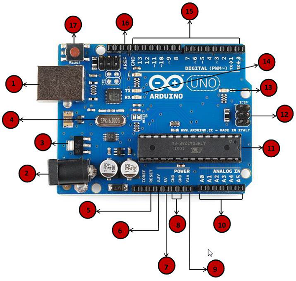
In this chapter, we will learn about the different components on the Arduino board. We will study the Arduino UNO board because it is the most popular board in the Arduino board family. In addition, it is the best board to get started with electronics and coding. Some boards look a bit different from the one given below, but most Arduinos have majority of these components in common.
 |
Power USB Arduino board can be powered by using the USB cable from your computer. All you need to do is connect the USB cable to the USB connection (1). |
 |
Power (Barrel Jack) Arduino boards can be powered directly from the AC mains power supply by connecting it to the Barrel Jack (2). |
 |
Voltage Regulator The function of the voltage regulator is to control the voltage given to the Arduino board and stabilize the DC voltages used by the processor and other elements. |
 |
Crystal Oscillator The crystal oscillator helps Arduino in dealing with time issues. How does Arduino calculate time? The answer is, by using the crystal oscillator. The number printed on top of the Arduino crystal is 16.000H9H. It tells us that the frequency is 16,000,000 Hertz or 16 MHz. |
 |
Arduino Reset You can reset your Arduino board, i.e., start your program from the beginning. You can reset the UNO board in two ways. First, by using the reset button (17) on the board. Second, you can connect an external reset button to the Arduino pin labelled RESET (5). |
 |
Pins (3.3, 5, GND, Vin)
|
 |
Analog pins The Arduino UNO board has six analog input pins A0 through A5. These pins can read the signal from an analog sensor like the humidity sensor or temperature sensor and convert it into a digital value that can be read by the microprocessor. |
 |
Main microcontroller Each Arduino board has its own microcontroller (11). You can assume it as the brain of your board. The main IC (integrated circuit) on the Arduino is slightly different from board to board. The microcontrollers are usually of the ATMEL Company. You must know what IC your board has before loading up a new program from the Arduino IDE. This information is available on the top of the IC. For more details about the IC construction and functions, you can refer to the data sheet. |
 |
ICSP pin Mostly, ICSP (12) is an AVR, a tiny programming header for the Arduino consisting of MOSI, MISO, SCK, RESET, VCC, and GND. It is often referred to as an SPI (Serial Peripheral Interface), which could be considered as an "expansion" of the output. Actually, you are slaving the output device to the master of the SPI bus. |
 |
Power LED indicator This LED should light up when you plug your Arduino into a power source to indicate that your board is powered up correctly. If this light does not turn on, then there is something wrong with the connection. |
 |
TX and RX LEDs On your board, you will find two labels: TX (transmit) and RX (receive). They appear in two places on the Arduino UNO board. First, at the digital pins 0 and 1, to indicate the pins responsible for serial communication. Second, the TX and RX led (13). The TX led flashes with different speed while sending the serial data. The speed of flashing depends on the baud rate used by the board. RX flashes during the receiving process. |
 |
Digital I/O The Arduino UNO board has 14 digital I/O pins (15) (of which 6 provide PWM (Pulse Width Modulation) output. These pins can be configured to work as input digital pins to read logic values (0 or 1) or as digital output pins to drive different modules like LEDs, relays, etc. The pins labeled ~ can be used to generate PWM. |
 |
AREF AREF stands for Analog Reference. It is sometimes, used to set an external reference voltage (between 0 and 5 Volts) as the upper limit for the analog input pins. |
Arduino - Installation
After learning about the main parts of the Arduino UNO board, we are ready to learn how to set up the Arduino IDE. Once we learn this, we will be ready to upload our program on the Arduino board.
In this section, we will learn in easy steps, how to set up the Arduino IDE on our computer and prepare the board to receive the program via USB cable.
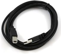
Step 1 − First you must have your Arduino board (you can choose your favorite board) and a USB cable. In case you use Arduino UNO, Arduino Duemilanove, Nano, Arduino Mega 2560, or Diecimila, you will need a standard USB cable (A plug to B plug), the kind you would connect to a USB printer as shown in the following image.
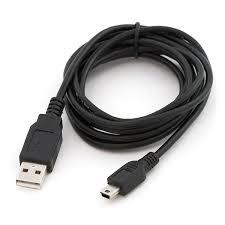
In case you use Arduino Nano, you will need an A to Mini-B cable instead as shown in the following image.
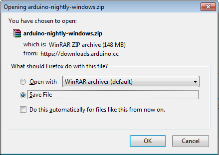
Step 2 − Download Arduino IDE Software.
You can get different versions of Arduino IDE from the Download page on the Arduino Official website. You must select your software, which is compatible with your operating system (Windows, IOS, or Linux). After your file download is complete, unzip the file.
Step 3 − Power up your board.
The Arduino Uno, Mega, Duemilanove and Arduino Nano automatically draw power from either, the USB connection to the computer or an external power supply. If you are using an Arduino Diecimila, you have to make sure that the board is configured to draw power from the USB connection. The power source is selected with a jumper, a small piece of plastic that fits onto two of the three pins between the USB and power jacks. Check that it is on the two pins closest to the USB port.
Connect the Arduino board to your computer using the USB cable. The green power LED (labeled PWR) should glow.
Step 4 − Launch Arduino IDE.
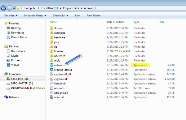
After your Arduino IDE software is downloaded, you need to unzip the folder. Inside the folder, you can find the application icon with an infinity label (application.exe). Double-click the icon to start the IDE.
Step 5 − Open your first project.
Once the software starts, you have two options −
- Create a new project.
- Open an existing project example.
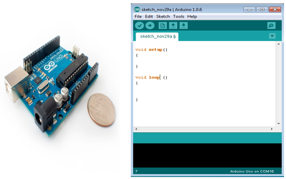
To create a new project, select File → New.
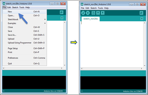
To open an existing project example, select File → Example → Basics → Blink.

Here, we are selecting just one of the examples with the name Blink. It turns the LED on and off with some time delay. You can select any other example from the list.
Step 6 − Select your Arduino board.
To avoid any error while uploading your program to the board, you must select the correct Arduino board name, which matches with the board connected to your computer.
Go to Tools → Board and select your board.
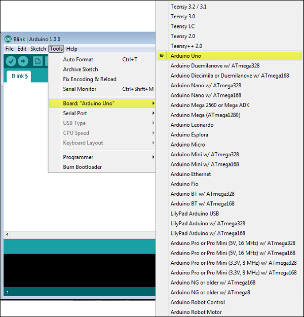
Here, we have selected Arduino Uno board according to our tutorial, but you must select the name matching the board that you are using.
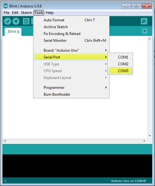
Step 7 − Select your serial port.
Select the serial device of the Arduino board. Go to Tools → Serial Port menu. This is likely to be COM3 or higher (COM1 and COM2 are usually reserved for hardware serial ports). To find out, you can disconnect your Arduino board and re-open the menu, the entry that disappears should be of the Arduino board. Reconnect the board and select that serial port.
Step 8 − Upload the program to your board.
Before explaining how we can upload our program to the board, we must demonstrate the function of each symbol appearing in the Arduino IDE toolbar.
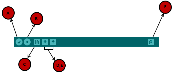
A − Used to check if there is any compilation error.
B − Used to upload a program to the Arduino board.
C − Shortcut used to create a new sketch.
D − Used to directly open one of the example sketch.
E − Used to save your sketch.
F − Serial monitor used to receive serial data from the board and send the serial data to the board.
Now, simply click the "Upload" button in the environment. Wait a few seconds; you will see the RX and TX LEDs on the board, flashing. If the upload is successful, the message "Done uploading" will appear in the status bar.
Note − If you have an Arduino Mini, NG, or other board, you need to press the reset button physically on the board, immediately before clicking the upload button on the Arduino Software.
Arduino - Program Structure
In this chapter, we will study in depth, the Arduino program structure and we will learn more new terminologies used in the Arduino world. The Arduino software is open-source. The source code for the Java environment is released under the GPL and the C/C++ microcontroller libraries are under the LGPL.
Sketch − The first new terminology is the Arduino program called sketch.
Structure
Arduino programs can be divided in three main parts: Structure, Values (variables and constants), and Functions. In this tutorial, we will learn about the Arduino software program, step by step, and how we can write the program without any syntax or compilation error.
Let us start with the Structure. Software structure consist of two main functions −
- Setup( ) function
- Loop( ) function
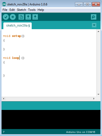
Void setup ( ) {

}
PURPOSE − The setup() function is called when a sketch starts. Use it to initialize the variables, pin modes, start using libraries, etc. The setup function will only run once, after each power up or reset of the Arduino board.
INPUT − -
OUTPUT − -
RETURN − -
Void Loop ( ) {

}
PURPOSE − After creating a setup() function, which initializes and sets the initial values, the loop() function does precisely what its name suggests, and loops consecutively, allowing your program to change and respond. Use it to actively control the Arduino board.
INPUT − -
OUTPUT − -
RETURN − -
Arduino - Data Types
Data types in C refers to an extensive system used for declaring variables or functions of different types. The type of a variable determines how much space it occupies in the storage and how the bit pattern stored is interpreted.
The following table provides all the data types that you will use during Arduino programming.
| void | Boolean | char | Unsigned char | byte | int | Unsigned int | word |
| long | Unsigned long | short | float | double | array | String-char array | String-object |
void
The void keyword is used only in function declarations. It indicates that the function is expected to return no information to the function from which it was called.
Example
Void Loop ( ) {
   // rest of the code
}
Boolean
A Boolean holds one of two values, true or false. Each Boolean variable occupies one byte of memory.
Example
boolean val = false ; // declaration of variable with type boolean and initialize it with false
boolean state = true ; // declaration of variable with type boolean and initialize it with true
Char
A data type that takes up one byte of memory that stores a character value. Character literals are written in single quotes like this: 'A' and for multiple characters, strings use double quotes: "ABC".
However, characters are stored as numbers. You can see the specific encoding in the ASCII chart. This means that it is possible to do arithmetic operations on characters, in which the ASCII value of the character is used. For example, 'A' + 1 has the value 66, since the ASCII value of the capital letter A is 65.
Example
Char chr_a = a ;//declaration of variable with type char and initialize it with character a
Char chr_c = 97 ;//declaration of variable with type char and initialize it with character 97

unsigned char
Unsigned char is an unsigned data type that occupies one byte of memory. The unsigned char data type encodes numbers from 0 to 255.
Example
Unsigned Char chr_y = 121 ; // declaration of variable with type Unsigned char and initialize it with character y
byte
A byte stores an 8-bit unsigned number, from 0 to 255.
Example
byte m = 25 ;//declaration of variable with type byte and initialize it with 25
int
Integers are the primary data-type for number storage. int stores a 16-bit (2-byte) value. This yields a range of -32,768 to 32,767 (minimum value of -2^15 and a maximum value of (2^15) - 1).
The int size varies from board to board. On the Arduino Due, for example, an int stores a 32-bit (4-byte) value. This yields a range of -2,147,483,648 to 2,147,483,647 (minimum value of -2^31 and a maximum value of (2^31) - 1).
Example
int counter = 32 ;// declaration of variable with type int and initialize it with 32
Unsigned int
Unsigned ints (unsigned integers) are the same as int in the way that they store a 2 byte value. Instead of storing negative numbers, however, they only store positive values, yielding a useful range of 0 to 65,535 (2^16) - 1). The Due stores a 4 byte (32-bit) value, ranging from 0 to 4,294,967,295 (2^32 - 1).
Example
Unsigned int counter = 60 ; // declaration of variable with
   type unsigned int and initialize it with 60
Word
On the Uno and other ATMEGA based boards, a word stores a 16-bit unsigned number. On the Due and Zero, it stores a 32-bit unsigned number.
Example
word w = 1000 ;//declaration of variable with type word and initialize it with 1000
Long
Long variables are extended size variables for number storage, and store 32 bits (4 bytes), from -2,147,483,648 to 2,147,483,647.
Example
Long velocity = 102346 ;//declaration of variable with type Long and initialize it with 102346
unsigned long
Unsigned long variables are extended size variables for number storage and store 32 bits (4 bytes). Unlike standard longs, unsigned longs will not store negative numbers, making their range from 0 to 4,294,967,295 (2^32 - 1).
Example
Unsigned Long velocity = 101006 ;// declaration of variable with
   type Unsigned Long and initialize it with 101006
short
A short is a 16-bit data-type. On all Arduinos (ATMega and ARM based), a short stores a 16-bit (2-byte) value. This yields a range of -32,768 to 32,767 (minimum value of -2^15 and a maximum value of (2^15) - 1).
Example
short val = 13 ;//declaration of variable with type short and initialize it with 13
float
Data type for floating-point number is a number that has a decimal point. Floating-point numbers are often used to approximate the analog and continuous values because they have greater resolution than integers.
Floating-point numbers can be as large as 3.4028235E+38 and as low as -3.4028235E+38. They are stored as 32 bits (4 bytes) of information.
Example
float num = 1.352;//declaration of variable with type float and initialize it with 1.352
double
On the Uno and other ATMEGA based boards, Double precision floating-point number occupies four bytes. That is, the double implementation is exactly the same as the float, with no gain in precision. On the Arduino Due, doubles have 8-byte (64 bit) precision.
Example
double num = 45.352 ;// declaration of variable with type double and initialize it with 45.352
Arduino - Variables & Constants
Before we start explaining the variable types, a very important subject we need to make sure, you fully understand is called the variable scope.
What is Variable Scope?
Variables in C programming language, which Arduino uses, have a property called scope. A scope is a region of the program and there are three places where variables can be declared. They are −
- Inside a function or a block, which is called local variables.
- In the definition of function parameters, which is called formal parameters.
- Outside of all functions, which is called global variables.
Local Variables
Variables that are declared inside a function or block are local variables. They can be used only by the statements that are inside that function or block of code. Local variables are not known to function outside their own. Following is the example using local variables −
Void setup () {

}

Void loop () {
   int x , y ;
   int z ; Local variable declaration
   x = 0;
   y = 0; actual initialization
   z = 10;
}
Global Variables
Global variables are defined outside of all the functions, usually at the top of the program. The global variables will hold their value throughout the life-time of your program.
A global variable can be accessed by any function. That is, a global variable is available for use throughout your entire program after its declaration.
The following example uses global and local variables −
Int T , S ;
float c = 0 ; Global variable declaration

Void setup () {

}

Void loop () {
   int x , y ;
   int z ; Local variable declaration
   x = 0;
   y = 0; actual initialization
   z = 10;
}
Arduino - Operators
An operator is a symbol that tells the compiler to perform specific mathematical or logical functions. C language is rich in built-in operators and provides the following types of operators −
- Arithmetic Operators
- Comparison Operators
- Boolean Operators
- Bitwise Operators
- Compound Operators
Arithmetic Operators
Assume variable A holds 10 and variable B holds 20 then −
| Operator name | Operator simple | Description | Example |
|---|---|---|---|
| assignment operator | = | Stores the value to the right of the equal sign in the variable to the left of the equal sign. | A = B |
| addition | + | Adds two operands | A + B will give 30 |
| subtraction | - | Subtracts second operand from the first | A - B will give -10 |
| multiplication | * | Multiply both operands | A * B will give 200 |
| division | / | Divide numerator by denominator | B / A will give 2 |
| modulo | % | Modulus Operator and remainder of after an integer division | B % A will give 0 |
Comparison Operators
Assume variable A holds 10 and variable B holds 20 then −
| Operator name | Operator simple | Description | Example |
|---|---|---|---|
| equal to | == | Checks if the value of two operands is equal or not, if yes then condition becomes true. | (A == B) is not true |
| not equal to | != | Checks if the value of two operands is equal or not, if values are not equal then condition becomes true. | (A != B) is true |
| less than | < | Checks if the value of left operand is less than the value of right operand, if yes then condition becomes true. | (A < B) is true |
| greater than | > | Checks if the value of left operand is greater than the value of right operand, if yes then condition becomes true. | (A > B) is not true |
| less than or equal to | <= | Checks if the value of left operand is less than or equal to the value of right operand, if yes then condition becomes true. | (A <= B) is true |
| greater than or equal to | >= | Checks if the value of left operand is greater than or equal to the value of right operand, if yes then condition becomes true. | (A >= B) is not true |
Boolean Operators
Assume variable A holds 10 and variable B holds 20 then −
| Operator name | Operator simple | Description | Example |
|---|---|---|---|
| and | && | Called Logical AND operator. If both the operands are non-zero then then condition becomes true. | (A && B) is true |
| or | || | Called Logical OR Operator. If any of the two operands is non-zero then then condition becomes true. | (A || B) is true |
| not | ! | Called Logical NOT Operator. Use to reverses the logical state of its operand. If a condition is true then Logical NOT operator will make false. | !(A && B) is false |
Bitwise Operators
Assume variable A holds 60 and variable B holds 13 then −
| Operator name | Operator simple | Description | Example |
|---|---|---|---|
| and | & | Binary AND Operator copies a bit to the result if it exists in both operands. | (A & B) will give 12 which is 0000 1100 |
| or | | | Binary OR Operator copies a bit if it exists in either operand | (A | B) will give 61 which is 0011 1101 |
| xor | ^ | Binary XOR Operator copies the bit if it is set in one operand but not both. | (A ^ B) will give 49 which is 0011 0001 |
| not | ~ | Binary Ones Complement Operator is unary and has the effect of 'flipping' bits. | (~A ) will give -60 which is 1100 0011 |
| shift left | << | Binary Left Shift Operator. The left operands value is moved left by the number of bits specified by the right operand. | A << 2 will give 240 which is 1111 0000 |
| shift right | >> | Binary Right Shift Operator. The left operands value is moved right by the number of bits specified by the right operand. | A >> 2 will give 15 which is 0000 1111 |
Compound Operators
Assume variable A holds 10 and variable B holds 20 then −
| Operator name | Operator simple | Description | Example |
|---|---|---|---|
| increment | ++ | Increment operator, increases integer value by one | A++ will give 11 |
| decrement | -- | Decrement operator, decreases integer value by one | A-- will give 9 |
| compound addition | += | Add AND assignment operator. It adds right operand to the left operand and assign the result to left operand | B += A is equivalent to B = B+ A |
| compound subtraction | -= | Subtract AND assignment operator. It subtracts right operand from the left operand and assign the result to left operand | B -= A is equivalent to B = B - A |
| compound multiplication | *= | Multiply AND assignment operator. It multiplies right operand with the left operand and assign the result to left operand | B*= A is equivalent to B = B* A |
| compound division | /= | Divide AND assignment operator. It divides left operand with the right operand and assign the result to left operand | B /= A is equivalent to B = B / A |
| compound modulo | %= | Modulus AND assignment operator. It takes modulus using two operands and assign the result to left operand | B %= A is equivalent to B = B % A |
| compound bitwise or | |= | bitwise inclusive OR and assignment operator | A |= 2 is same as A = A | 2 |
| compound bitwise and | &= | Bitwise AND assignment operator | A &= 2 is same as A = A & 2 |
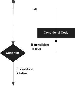
Arduino - Control Statements
Decision making structures require that the programmer specify one or more conditions to be evaluated or tested by the program. It should be along with a statement or statements to be executed if the condition is determined to be true, and optionally, other statements to be executed if the condition is determined to be false.
Following is the general form of a typical decision making structure found in most of the programming languages −
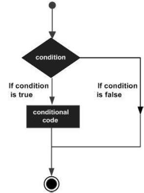
Control Statements are elements in Source Code that control the flow of program execution. They are −
| S.NO. | Control Statement & Description |
|---|---|
| 1 |
It takes an expression in parenthesis and a statement or block of statements. If the expression is true then the statement or block of statements gets executed otherwise these statements are skipped. |
| 2 |
An if statement can be followed by an optional else statement, which executes when the expression is false. |
| 3 |
The if statement can be followed by an optional else if...else statement, which is very useful to test various conditions using single if...else if statement. |
| 4 |
Similar to the if statements, switch...case controls the flow of programs by allowing the programmers to specify different codes that should be executed in various conditions. |
| 5 |
The conditional operator ? : is the only ternary operator in C. |
Arduino - Loops
Programming languages provide various control structures that allow for more complicated execution paths.
A loop statement allows us to execute a statement or group of statements multiple times and following is the general form of a loop statement in most of the programming languages −
C programming language provides the following types of loops to handle looping requirements.
| S.NO. | Loop & Description |
|---|---|
| 1 |
while loops will loop continuously, and infinitely, until the expression inside the parenthesis, () becomes false. Something must change the tested variable, or the while loop will never exit. |
| 2 |
The dowhile loop is similar to the while loop. In the while loop, the loop-continuation condition is tested at the beginning of the loop before performed the body of the loop. |
| 3 |
A for loop executes statements a predetermined number of times. The control expression for the loop is initialized, tested and manipulated entirely within the for loop parentheses. |
| 4 |
C language allows you to use one loop inside another loop. The following example illustrates the concept. |
| 5 |
It is the loop having no terminating condition, so the loop becomes infinite. |
Arduino - Functions
Functions allow structuring the programs in segments of code to perform individual tasks. The typical case for creating a function is when one needs to perform the same action multiple times in a program.
Standardizing code fragments into functions has several advantages −
Functions help the programmer stay organized. Often this helps to conceptualize the program.
Functions codify one action in one place so that the function only has to be thought about and debugged once.
This also reduces chances for errors in modification, if the code needs to be changed.
Functions make the whole sketch smaller and more compact because sections of code are reused many times.
They make it easier to reuse code in other programs by making it modular, and using functions often makes the code more readable.
There are two required functions in an Arduino sketch or a program i.e. setup () and loop(). Other functions must be created outside the brackets of these two functions.
The most common syntax to define a function is −
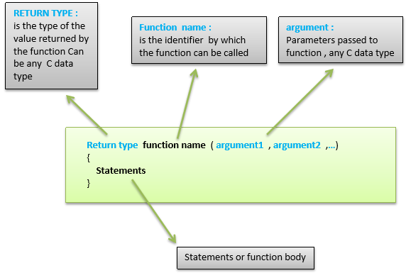
Function Declaration
A function is declared outside any other functions, above or below the loop function.
We can declare the function in two different ways −
The first way is just writing the part of the function called a function prototype above the loop function, which consists of −
- Function return type
- Function name
- Function argument type, no need to write the argument name
Function prototype must be followed by a semicolon ( ; ).
The following example shows the demonstration of the function declaration using the first method.
Example
int sum_func (int x, int y) // function declaration {
   int z = 0;
   z = x+y ;
   return z; // return the value
}

void setup () {
   Statements // group of statements
}

Void loop () {
   int result = 0 ;
   result = Sum_func (5,6) ; // function call
}
The second part, which is called the function definition or declaration, must be declared below the loop function, which consists of −
- Function return type
- Function name
- Function argument type, here you must add the argument name
- The function body (statements inside the function executing when the function is called)
The following example demonstrates the declaration of function using the second method.
Example
int sum_func (int , int ) ; // function prototype

void setup () {
   Statements // group of statements
}

Void loop () {
   int result = 0 ;
   result = Sum_func (5,6) ; // function call
}

int sum_func (int x, int y) // function declaration {
   int z = 0;
   z = x+y ;
   return z; // return the value
}
The second method just declares the function above the loop function.
Arduino - Strings
Strings are used to store text. They can be used to display text on an LCD or in the Arduino IDE Serial Monitor window. Strings are also useful for storing the user input. For example, the characters that a user types on a keypad connected to the Arduino.
There are two types of strings in Arduino programming −
- Arrays of characters, which are the same as the strings used in C programming.
- The Arduino String, which lets us use a string object in a sketch.
In this chapter, we will learn Strings, objects and the use of strings in Arduino sketches. By the end of the chapter, you will learn which type of string to use in a sketch.
String Character Arrays
The first type of string that we will learn is the string that is a series of characters of the type char. In the previous chapter, we learned what an array is; a consecutive series of the same type of variable stored in memory. A string is an array of char variables.
A string is a special array that has one extra element at the end of the string, which always has the value of 0 (zero). This is known as a "null terminated string".
String Character Array Example
This example will show how to make a string and print it to the serial monitor window.
Example
void setup() {
   char my_str[6]; // an array big enough for a 5 character string
   Serial.begin(9600);
   my_str[0] = 'H'; // the string consists of 5 characters
   my_str[1] = 'e';
   my_str[2] = 'l';
   my_str[3] = 'l';
   my_str[4] = 'o';
   my_str[5] = 0; // 6th array element is a null terminator
   Serial.println(my_str);
}

void loop() {

}
The following example shows what a string is made up of; a character array with printable characters and 0 as the last element of the array to show that this is where the string ends. The string can be printed out to the Arduino IDE Serial Monitor window by using Serial.println() and passing the name of the string.
This same example can be written in a more convenient way as shown below −
Example
void setup() {
   char my_str[] = "Hello";
   Serial.begin(9600);
   Serial.println(my_str);
}

void loop() {

}
In this sketch, the compiler calculates the size of the string array and also automatically null terminates the string with a zero. An array that is six elements long and consists of five characters followed by a zero is created exactly the same way as in the previous sketch.
Manipulating String Arrays
We can alter a string array within a sketch as shown in the following sketch.
Example
void setup() {
   char like[] = "I like coffee and cake"; // create a string
   Serial.begin(9600);
   // (1) print the string
   Serial.println(like);
   // (2) delete part of the string
   like[13] = 0;
   Serial.println(like);
   // (3) substitute a word into the string
   like[13] = ' '; // replace the null terminator with a space
   like[18] = 't'; // insert the new word
   like[19] = 'e';
   like[20] = 'a';
   like[21] = 0; // terminate the string
   Serial.println(like);
}

void loop() {

}
Result
I like coffee and cake
I like coffee
I like coffee and tea
The sketch works in the following way.
Creating and Printing the String
In the sketch given above, a new string is created and then printed for display in the Serial Monitor window.
Shortening the String
The string is shortened by replacing the 14th character in the string with a null terminating zero (2). This is element number 13 in the string array counting from 0.
When the string is printed, all the characters are printed up to the new null terminating zero. The other characters do not disappear; they still exist in the memory and the string array is still the same size. The only difference is that any function that works with strings will only see the string up to the first null terminator.
Changing a Word in the String
Finally, the sketch replaces the word "cake" with "tea" (3). It first has to replace the null terminator at like[13] with a space so that the string is restored to the originally created format.
New characters overwrite "cak" of the word "cake" with the word "tea". This is done by overwriting individual characters. The 'e' of "cake" is replaced with a new null terminating character. The result is that the string is actually terminated with two null characters, the original one at the end of the string and the new one that replaces the 'e' in "cake". This makes no difference when the new string is printed because the function that prints the string stops printing the string characters when it encounters the first null terminator.
Functions to Manipulate String Arrays
The previous sketch manipulated the string in a manual way by accessing individual characters in the string. To make it easier to manipulate string arrays, you can write your own functions to do so, or use some of the string functions from the C language library.
The next sketch uses some C string functions.
Example
void setup() {
   char str[] = "This is my string"; // create a string
   char out_str[40]; // output from string functions placed here
   int num; // general purpose integer
   Serial.begin(9600);

   // (1) print the string
   Serial.println(str);

   // (2) get the length of the string (excludes null terminator)
   num = strlen(str);
   Serial.print("String length is: ");
   Serial.println(num);

   // (3) get the length of the array (includes null terminator)
   num = sizeof(str); // sizeof() is not a C string function
   Serial.print("Size of the array: ");
   Serial.println(num);

   // (4) copy a string
   strcpy(out_str, str);
   Serial.println(out_str);

   // (5) add a string to the end of a string (append)
   strcat(out_str, " sketch.");
   Serial.println(out_str);
   num = strlen(out_str);
   Serial.print("String length is: ");
   Serial.println(num);
   num = sizeof(out_str);
   Serial.print("Size of the array out_str[]: ");
   Serial.println(num);
}

void loop() {

}
Result
This is my string
String length is: 17
Size of the array: 18
This is my string
This is my string sketch.
String length is: 25
Size of the array out_str[]: 40
The sketch works in the following way.
Print the String
The newly created string is printed to the Serial Monitor window as done in previous sketches.
Get the Length of the String
The strlen() function is used to get the length of the string. The length of the string is for the printable characters only and does not include the null terminator.
The string contains 17 characters, so we see 17 printed in the Serial Monitor window.
Get the Length of the Array
The operator sizeof() is used to get the length of the array that contains the string. The length includes the null terminator, so the length is one more than the length of the string.
sizeof() looks like a function, but technically is an operator. It is not a part of the C string library, but was used in the sketch to show the difference between the size of the array and the size of the string (or string length).
Copy a String
The strcpy() function is used to copy the str[] string to the out_num[] array. The strcpy() function copies the second string passed to it into the first string. A copy of the string now exists in the out_num[] array, but only takes up 18 elements of the array, so we still have 22 free char elements in the array. These free elements are found after the string in memory.
The string was copied to the array so that we would have some extra space in the array to use in the next part of the sketch, which is adding a string to the end of a string.
Append a String to a String (Concatenate)
The sketch joins one string to another, which is known as concatenation. This is done using the strcat() function. The strcat() function puts the second string passed to it onto the end of the first string passed to it.
After concatenation, the length of the string is printed to show the new string length. The length of the array is then printed to show that we have a 25-character long string in a 40 element long array.
Remember that the 25-character long string actually takes up 26 characters of the array because of the null terminating zero.
Array Bounds
When working with strings and arrays, it is very important to work within the bounds of strings or arrays. In the example sketch, an array was created, which was 40 characters long, in order to allocate the memory that could be used to manipulate strings.
If the array was made too small and we tried to copy a string that is bigger than the array to it, the string would be copied over the end of the array. The memory beyond the end of the array could contain other important data used in the sketch, which would then be overwritten by our string. If the memory beyond the end of the string is overrun, it could crash the sketch or cause unexpected behavior.
Arduino - String Object
The second type of string used in Arduino programming is the String Object.
What is an Object?
An object is a construct that contains both data and functions. A String object can be created just like a variable and assigned a value or string. The String object contains functions (which are called "methods" in object oriented programming (OOP)) which operate on the string data contained in the String object.
The following sketch and explanation will make it clear what an object is and how the String object is used.
Example
void setup() {
   String my_str = "This is my string.";
   Serial.begin(9600);

   // (1) print the string
   Serial.println(my_str);

   // (2) change the string to upper-case
   my_str.toUpperCase();
   Serial.println(my_str);

   // (3) overwrite the string
   my_str = "My new string.";
   Serial.println(my_str);

   // (4) replace a word in the string
   my_str.replace("string", "Arduino sketch");
   Serial.println(my_str);

   // (5) get the length of the string
   Serial.print("String length is: ");
   Serial.println(my_str.length());
}

void loop() {

}
Result
This is my string.
THIS IS MY STRING.
My new string.
My new Arduino sketch.
String length is: 22
A string object is created and assigned a value (or string) at the top of the sketch.
String my_str = "This is my string." ;
This creates a String object with the name my_str and gives it a value of "This is my string.".
This can be compared to creating a variable and assigning a value to it such as an integer −
int my_var = 102;
The sketch works in the following way.
Printing the String
The string can be printed to the Serial Monitor window just like a character array string.
Convert the String to Upper-case
The string object my_str that was created, has a number of functions or methods that can be operated on it. These methods are invoked by using the objects name followed by the dot operator (.) and then the name of the function to use.
my_str.toUpperCase();
The toUpperCase() function operates on the string contained in the my_str object which is of type String and converts the string data (or text) that the object contains to upper-case characters. A list of the functions that the String class contains can be found in the Arduino String reference. Technically, String is called a class and is used to create String objects.
Overwrite a String
The assignment operator is used to assign a new string to the my_str object that replaces the old string
my_str = "My new string." ;
The assignment operator cannot be used on character array strings, but works on String objects only.
Replacing a Word in the String
The replace() function is used to replace the first string passed to it by the second string passed to it. replace() is another function that is built into the String class and so is available to use on the String object my_str.
Getting the Length of the String
Getting the length of the string is easily done by using length(). In the example sketch, the result returned by length() is passed directly to Serial.println() without using an intermediate variable.
When to Use a String Object
A String object is much easier to use than a string character array. The object has built-in functions that can perform a number of operations on strings.
The main disadvantage of using the String object is that it uses a lot of memory and can quickly use up the Arduinos RAM memory, which may cause Arduino to hang, crash or behave unexpectedly. If a sketch on an Arduino is small and limits the use of objects, then there should be no problems.
Character array strings are more difficult to use and you may need to write your own functions to operate on these types of strings. The advantage is that you have control on the size of the string arrays that you make, so you can keep the arrays small to save memory.
You need to make sure that you do not write beyond the end of the array bounds with string arrays. The String object does not have this problem and will take care of the string bounds for you, provided there is enough memory for it to operate on. The String object can try to write to memory that does not exist when it runs out of memory, but will never write over the end of the string that it is operating on.
Where Strings are Used
In this chapter we studied about the strings, how they behave in memory and their operations.
The practical uses of strings will be covered in the next part of this course when we study how to get user input from the Serial Monitor window and save the input in a string.
Arduino - Time
Arduino provides four different time manipulation functions. They are −
| S.No. | Function & Description |
|---|---|
| 1 |
The way the delay() function works is pretty simple. It accepts a single integer (or number) argument. This number represents the time (measured in milliseconds). |
| 2 |
The delayMicroseconds() function accepts a single integer (or number) argument. There are a thousand microseconds in a millisecond, and a million microseconds in a second. |
| 3 |
This function is used to return the number of milliseconds at the time, the Arduino board begins running the current program. |
| 4 |
The micros() function returns the number of microseconds from the time, the Arduino board begins running the current program. This number overflows i.e. goes back to zero after approximately 70 minutes. |
Arduino - Arrays
An array is a consecutive group of memory locations that are of the same type. To refer to a particular location or element in the array, we specify the name of the array and the position number of the particular element in the array.
The illustration given below shows an integer array called C that contains 11 elements. You refer to any one of these elements by giving the array name followed by the particular elements position number in square brackets ([]). The position number is more formally called a subscript or index (this number specifies the number of elements from the beginning of the array). The first element has subscript 0 (zero) and is sometimes called the zeros element.
Thus, the elements of array C are C[0] (pronounced C sub zero), C[1], C[2] and so on. The highest subscript in array C is 10, which is 1 less than the number of elements in the array (11). Array names follow the same conventions as other variable names.
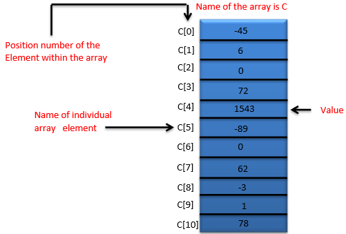
A subscript must be an integer or integer expression (using any integral type). If a program uses an expression as a subscript, then the program evaluates the expression to determine the subscript. For example, if we assume that variable a is equal to 5 and that variable b is equal to 6, then the statement adds 2 to array element C[11].
A subscripted array name is an lvalue, it can be used on the left side of an assignment, just as non-array variable names can.
Let us examine array C in the given figure, more closely. The name of the entire array is C. Its 11 elements are referred to as C[0] to C[10]. The value of C[0] is -45, the value of C[1] is 6, the value of C[2] is 0, the value of C[7] is 62, and the value of C[10] is 78.
To print the sum of the values contained in the first three elements of array C, we would write −
Serial.print (C[ 0 ] + C[ 1 ] + C[ 2 ] );
To divide the value of C[6] by 2 and assign the result to the variable x, we would write −
x = C[ 6 ] / 2;
Declaring Arrays
Arrays occupy space in memory. To specify the type of the elements and the number of elements required by an array, use a declaration of the form −
type arrayName [ arraySize ] ;
The compiler reserves the appropriate amount of memory. (Recall that a declaration, which reserves memory is more properly known as a definition). The arraySize must be an integer constant greater than zero. For example, to tell the compiler to reserve 11 elements for integer array C, use the declaration −
int C[ 12 ]; // C is an array of 12 integers
Arrays can be declared to contain values of any non-reference data type. For example, an array of type string can be used to store character strings.
Examples Using Arrays
This section gives many examples that demonstrate how to declare, initialize and manipulate arrays.
Example 1: Declaring an Array and using a Loop to Initialize the Arrays Elements
The program declares a 10-element integer array n. Lines ab use a For statement to initialize the array elements to zeros. Like other automatic variables, automatic arrays are not implicitly initialized to zero. The first output statement (line c) displays the column headings for the columns printed in the subsequent for statement (lines de), which prints the array in tabular format.
Example
int n[ 10 ] ; // n is an array of 10 integers

void setup () {

}

void loop () {
   for ( int i = 0; i < 10; ++i ) // initialize elements of array n to 0 {
      n[ i ] = 0; // set element at location i to 0
      Serial.print (i) ;
      Serial.print (\r) ;
   }
   for ( int j = 0; j < 10; ++j ) // output each array element's value {
      Serial.print (n[j]) ;
      Serial.print (\r) ;
   }
}
Result − It will produce the following result −
Element
Value


0
1
2
3
4
5
6
7
8
9


0
0
0
0
0
0
0
0
0
0
Example 2: Initializing an Array in a Declaration with an Initializer List
The elements of an array can also be initialized in the array declaration by following the array name with an equal-to sign and a brace-delimited comma-separated list of initializers. The program uses an initializer list to initialize an integer array with 10 values (line a) and prints the array in tabular format (lines bc).
Example
// n is an array of 10 integers
int n[ 10 ] = { 32, 27, 64, 18, 95, 14, 90, 70, 60, 37 } ;

void setup () {

}

void loop () {
   for ( int i = 0; i < 10; ++i ) {
      Serial.print (i) ;
      Serial.print (\r) ;
   }
   for ( int j = 0; j < 10; ++j ) // output each array element's value {
      Serial.print (n[j]) ;
      Serial.print (\r) ;
   }
}
Result − It will produce the following result −
Element
Value


0
1
2
3
4
5
6
7
8
9


32
27
64
18
95
14
90
70
60
37
Example 3: Summing the Elements of an Array
Often, the elements of an array represent a series of values to be used in a calculation. For example, if the elements of an array represent exam grades, a professor may wish to total the elements of the array and use that sum to calculate the class average for the exam. The program sums the values contained in the 10-element integer array a.
Example
const int arraySize = 10; // constant variable indicating size of array
int a[ arraySize ] = { 87, 68, 94, 100, 83, 78, 85, 91, 76, 87 };
int total = 0;

void setup () {

}
void loop () {
   // sum contents of array a
   for ( int i = 0; i < arraySize; ++i )
      total += a[ i ];
   Serial.print (Total of array elements : ) ;
   Serial.print(total) ;
}
Result − It will produce the following result −
Total of array elements: 849
Arrays are important to Arduino and should need a lot more attention. The following important concepts related to array should be clear to a Arduino −
| S.NO. | Concept & Description |
|---|---|
| 1 | Passing Arrays to Functions
To pass an array argument to a function, specify the name of the array without any brackets. |
| 2 | Multi-Dimensional Arrays
Arrays with two dimensions (i.e., subscripts) often represent tables of values consisting of information arranged in rows and columns. |
Arduino - I/O Functions
The pins on the Arduino board can be configured as either inputs or outputs. We will explain the functioning of the pins in those modes. It is important to note that a majority of Arduino analog pins, may be configured, and used, in exactly the same manner as digital pins.
Pins Configured as INPUT
Arduino pins are by default configured as inputs, so they do not need to be explicitly declared as inputs with pinMode() when you are using them as inputs. Pins configured this way are said to be in a high-impedance state. Input pins make extremely small demands on the circuit that they are sampling, equivalent to a series resistor of 100 megaohm in front of the pin.
This means that it takes very little current to switch the input pin from one state to another. This makes the pins useful for such tasks as implementing a capacitive touch sensor or reading an LED as a photodiode.
Pins configured as pinMode(pin, INPUT) with nothing connected to them, or with wires connected to them that are not connected to other circuits, report seemingly random changes in pin state, picking up electrical noise from the environment, or capacitively coupling the state of a nearby pin.
Pull-up Resistors
Pull-up resistors are often useful to steer an input pin to a known state if no input is present. This can be done by adding a pull-up resistor (to +5V), or a pull-down resistor (resistor to ground) on the input. A 10K resistor is a good value for a pull-up or pull-down resistor.
Using Built-in Pull-up Resistor with Pins Configured as Input
There are 20,000 pull-up resistors built into the Atmega chip that can be accessed from software. These built-in pull-up resistors are accessed by setting the pinMode() as INPUT_PULLUP. This effectively inverts the behavior of the INPUT mode, where HIGH means the sensor is OFF and LOW means the sensor is ON. The value of this pull-up depends on the microcontroller used. On most AVR-based boards, the value is guaranteed to be between 20k and 50k. On the Arduino Due, it is between 50k and 150k. For the exact value, consult the datasheet of the microcontroller on your board.
When connecting a sensor to a pin configured with INPUT_PULLUP, the other end should be connected to the ground. In case of a simple switch, this causes the pin to read HIGH when the switch is open and LOW when the switch is pressed. The pull-up resistors provide enough current to light an LED dimly connected to a pin configured as an input. If LEDs in a project seem to be working, but very dimly, this is likely what is going on.
Same registers (internal chip memory locations) that control whether a pin is HIGH or LOW control the pull-up resistors. Consequently, a pin that is configured to have pull-up resistors turned on when the pin is in INPUTmode, will have the pin configured as HIGH if the pin is then switched to an OUTPUT mode with pinMode(). This works in the other direction as well, and an output pin that is left in a HIGH state will have the pull-up resistor set if switched to an input with pinMode().
Example
pinMode(3,INPUT) ; // set pin to input without using built in pull up resistor
pinMode(5,INPUT_PULLUP) ; // set pin to input using built in pull up resistor
Pins Configured as OUTPUT
Pins configured as OUTPUT with pinMode() are said to be in a low-impedance state. This means that they can provide a substantial amount of current to other circuits. Atmega pins can source (provide positive current) or sink (provide negative current) up to 40 mA (milliamps) of current to other devices/circuits. This is enough current to brightly light up an LED (do not forget the series resistor), or run many sensors but not enough current to run relays, solenoids, or motors.
Attempting to run high current devices from the output pins, can damage or destroy the output transistors in the pin, or damage the entire Atmega chip. Often, this results in a "dead" pin in the microcontroller but the remaining chips still function adequately. For this reason, it is a good idea to connect the OUTPUT pins to other devices through 470 or 1k resistors, unless maximum current drawn from the pins is required for a particular application.
pinMode() Function
The pinMode() function is used to configure a specific pin to behave either as an input or an output. It is possible to enable the internal pull-up resistors with the mode INPUT_PULLUP. Additionally, the INPUT mode explicitly disables the internal pull-ups.
pinMode() Function Syntax
Void setup () {
   pinMode (pin , mode);
}
pin − the number of the pin whose mode you wish to set
mode − INPUT, OUTPUT, or INPUT_PULLUP.
Example
int button = 5 ; // button connected to pin 5
int LED = 6; // LED connected to pin 6

void setup () {
   pinMode(button , INPUT_PULLUP);
   // set the digital pin as input with pull-up resistor
   pinMode(button , OUTPUT); // set the digital pin as output
}

void setup () {
   If (digitalRead(button ) == LOW) // if button pressed {
      digitalWrite(LED,HIGH); // turn on led
      delay(500); // delay for 500 ms
      digitalWrite(LED,LOW); // turn off led
      delay(500); // delay for 500 ms
   }
}
digitalWrite() Function
The digitalWrite() function is used to write a HIGH or a LOW value to a digital pin. If the pin has been configured as an OUTPUT with pinMode(), its voltage will be set to the corresponding value: 5V (or 3.3V on 3.3V boards) for HIGH, 0V (ground) for LOW. If the pin is configured as an INPUT, digitalWrite() will enable (HIGH) or disable (LOW) the internal pullup on the input pin. It is recommended to set the pinMode() to INPUT_PULLUP to enable the internal pull-up resistor.
If you do not set the pinMode() to OUTPUT, and connect an LED to a pin, when calling digitalWrite(HIGH), the LED may appear dim. Without explicitly setting pinMode(), digitalWrite() will have enabled the internal pull-up resistor, which acts like a large current-limiting resistor.
digitalWrite() Function Syntax
Void loop() {
   digitalWrite (pin ,value);
}
pin − the number of the pin whose mode you wish to set
value − HIGH, or LOW.
Example
int LED = 6; // LED connected to pin 6

void setup () {
   pinMode(LED, OUTPUT); // set the digital pin as output
}

void setup () {
   digitalWrite(LED,HIGH); // turn on led
   delay(500); // delay for 500 ms
   digitalWrite(LED,LOW); // turn off led
   delay(500); // delay for 500 ms
}
analogRead( ) function
Arduino is able to detect whether there is a voltage applied to one of its pins and report it through the digitalRead() function. There is a difference between an on/off sensor (which detects the presence of an object) and an analog sensor, whose value continuously changes. In order to read this type of sensor, we need a different type of pin.
In the lower-right part of the Arduino board, you will see six pins marked Analog In. These special pins not only tell whether there is a voltage applied to them, but also its value. By using the analogRead() function, we can read the voltage applied to one of the pins.
This function returns a number between 0 and 1023, which represents voltages between 0 and 5 volts. For example, if there is a voltage of 2.5 V applied to pin number 0, analogRead(0) returns 512.
analogRead() function Syntax
analogRead(pin);
pin − the number of the analog input pin to read from (0 to 5 on most boards, 0 to 7 on the Mini and Nano, 0 to 15 on the Mega)
Example
int analogPin = 3;//potentiometer wiper (middle terminal)
   // connected to analog pin 3
int val = 0; // variable to store the value read

void setup() {
   Serial.begin(9600); // setup serial
}

void loop() {
   val = analogRead(analogPin); // read the input pin
   Serial.println(val); // debug value
}
Arduino - Advanced I/O Function
In this chapter, we will learn some advanced Input and Output Functions.
analogReference() Function
Configures the reference voltage used for analog input (i.e. the value used as the top of the input range). The options are −
DEFAULT − The default analog reference of 5 volts (on 5V Arduino boards) or 3.3 volts (on 3.3V Arduino boards)
INTERNAL − An built-in reference, equal to 1.1 volts on the ATmega168 or ATmega328 and 2.56 volts on the ATmega8 (not available on the Arduino Mega)
INTERNAL1V1 − A built-in 1.1V reference (Arduino Mega only)
INTERNAL2V56 − A built-in 2.56V reference (Arduino Mega only)
EXTERNAL − The voltage applied to the AREF pin (0 to 5V only) is used as the reference
analogReference() Function Syntax
analogReference (type);
type − can use any type of the follow (DEFAULT, INTERNAL, INTERNAL1V1, INTERNAL2V56, EXTERNAL)
Do not use anything less than 0V or more than 5V for external reference voltage on the AREF pin. If you are using an external reference on the AREF pin, you must set the analog reference to EXTERNAL before calling the analogRead() function. Otherwise, you will short the active reference voltage (internally generated) and the AREF pin, possibly damaging the microcontroller on your Arduino board.
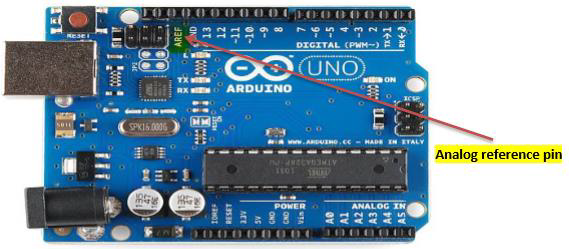
Alternatively, you can connect the external reference voltage to the AREF pin through a 5K resistor, allowing you to switch between external and internal reference voltages.
Note that the resistor will alter the voltage that is used as the reference because there is an internal 32K resistor on the AREF pin. The two act as a voltage divider. For example, 2.5V applied through the resistor will yield 2.5 * 32 / (32 + 5) = ~2.2V at the AREF pin.
Example
int analogPin = 3;// potentiometer wiper (middle terminal) connected to analog pin 3
int val = 0; // variable to store the read value

void setup() {
   Serial.begin(9600); // setup serial
   analogReference(EXTERNAL); // the voltage applied to the AREF pin (0 to 5V only)
      // is used as the reference.
}

void loop() {
   val = analogRead(analogPin); // read the input pin
   Serial.println(val); // debug value
}
Arduino - Character Functions
All data is entered into computers as characters, which includes letters, digits and various special symbols. In this section, we discuss the capabilities of C++ for examining and manipulating individual characters.
The character-handling library includes several functions that perform useful tests and manipulations of character data. Each function receives a character, represented as an int, or EOF as an argument. Characters are often manipulated as integers.
Remember that EOF normally has the value 1 and that some hardware architectures do not allow negative values to be stored in char variables. Therefore, the character-handling functions manipulate characters as integers.
The following table summarizes the functions of the character-handling library. When using functions from the character-handling library, include the <cctype> header.
| S.No. | Prototype & Description |
|---|---|
| 1 |
int isdigit( int c ) Returns 1 if c is a digit and 0 otherwise. |
| 2 |
int isalpha( int c ) Returns 1 if c is a letter and 0 otherwise. |
| 3 |
int isalnum( int c ) Returns 1 if c is a digit or a letter and 0 otherwise. |
| 4 |
int isxdigit( int c ) Returns 1 if c is a hexadecimal digit character and 0 otherwise. (See Appendix D, Number Systems, for a detailed explanation of binary, octal, decimal and hexadecimal numbers.) |
| 5 |
int islower( int c ) Returns 1 if c is a lowercase letter and 0 otherwise. |
| 6 |
int isupper( int c ) Returns 1 if c is an uppercase letter; 0 otherwise. |
| 7 |
int isspace( int c ) Returns 1 if c is a white-space characternewline ('\n'), space (' '), form feed ('\f'), carriage return ('\r'), horizontal tab ('\t'), or vertical tab ('\v')and 0 otherwise. |
| 8 |
int iscntrl( int c ) Returns 1 if c is a control character, such as newline ('\n'), form feed ('\f'), carriage return ('\r'), horizontal tab ('\t'), vertical tab ('\v'), alert ('\a'), or backspace ('\b')and 0 otherwise. |
| 9 |
int ispunct( int c ) Returns 1 if c is a printing character other than a space, a digit, or a letter and 0 otherwise. |
| 10 |
int isprint( int c ) Returns 1 if c is a printing character including space (' ') and 0 otherwise. |
| 11 |
int isgraph( int c ) Returns 1 if c is a printing character other than space (' ') and 0 otherwise. |
Examples
The following example demonstrates the use of the functions isdigit, isalpha, isalnum and isxdigit. Function isdigit determines whether its argument is a digit (09). The function isalpha determines whether its argument is an uppercase letter (A-Z) or a lowercase letter (az). The function isalnum determines whether its argument is an uppercase, lowercase letter or a digit. Function isxdigit determines whether its argument is a hexadecimal digit (AF, af, 09).
Example 1
void setup () {
   Serial.begin (9600);
   Serial.print ("According to isdigit:\r");
   Serial.print (isdigit( '8' ) ? "8 is a": "8 is not a");
   Serial.print (" digit\r" );
   Serial.print (isdigit( '8' ) ?"# is a": "# is not a") ;
   Serial.print (" digit\r");
   Serial.print ("\rAccording to isalpha:\r" );
   Serial.print (isalpha('A' ) ?"A is a": "A is not a");
   Serial.print (" letter\r");
   Serial.print (isalpha('A' ) ?"b is a": "b is not a");
   Serial.print (" letter\r");
   Serial.print (isalpha('A') ?"& is a": "& is not a");
   Serial.print (" letter\r");
   Serial.print (isalpha( 'A' ) ?"4 is a":"4 is not a");
   Serial.print (" letter\r");
   Serial.print ("\rAccording to isalnum:\r");
   Serial.print (isalnum( 'A' ) ?"A is a" : "A is not a" );

   Serial.print (" digit or a letter\r" );
   Serial.print (isalnum( '8' ) ?"8 is a" : "8 is not a" ) ;
   Serial.print (" digit or a letter\r");
   Serial.print (isalnum( '#' ) ?"# is a" : "# is not a" );
   Serial.print (" digit or a letter\r");
   Serial.print ("\rAccording to isxdigit:\r");
   Serial.print (isxdigit( 'F' ) ?"F is a" : "F is not a" );
   Serial.print (" hexadecimal digit\r" );
   Serial.print (isxdigit( 'J' ) ?"J is a" : "J is not a" ) ;
   Serial.print (" hexadecimal digit\r" );
   Serial.print (isxdigit( '7' ) ?"7 is a" : "7 is not a" ) ;

   Serial.print (" hexadecimal digit\r" );
   Serial.print (isxdigit( '$' ) ? "$ is a" : "$ is not a" );
   Serial.print (" hexadecimal digit\r" );
   Serial.print (isxdigit( 'f' ) ? f is a" : "f is not a");

}

void loop () {

}
Result
According to isdigit:
8 is a digit
# is not a digit
According to isalpha:
A is a letter
b is a letter
& is not a letter
4 is not a letter
According to isalnum:
A is a digit or a letter

8 is a digit or a letter
# is not a digit or a letter
According to isxdigit:
F is a hexadecimal digit
J is not a hexadecimal digit
7 is a hexadecimal digit

$ is not a hexadecimal digit
f is a hexadecimal digit
We use the conditional operator (?:) with each function to determine whether the string " is a " or the string " is not a " should be printed in the output for each character tested. For example, line a indicates that if '8' is a digiti.e., if isdigit returns a true (nonzero) valuethe string "8 is a " is printed. If '8' is not a digit (i.e., if isdigit returns 0), the string " 8 is not a " is printed.
Example 2
The following example demonstrates the use of the functions islower and isupper. The function islower determines whether its argument is a lowercase letter (az). Function isupper determines whether its argument is an uppercase letter (AZ).
int thisChar = 0xA0;

void setup () {
   Serial.begin (9600);
   Serial.print ("According to islower:\r") ;
   Serial.print (islower( 'p' ) ? "p is a" : "p is not a" );
   Serial.print ( " lowercase letter\r" );
   Serial.print ( islower( 'P') ? "P is a" : "P is not a") ;
   Serial.print ("lowercase letter\r");
   Serial.print (islower( '5' ) ? "5 is a" : "5 is not a" );
   Serial.print ( " lowercase letter\r" );
   Serial.print ( islower( '!' )? "! is a" : "! is not a") ;
   Serial.print ("lowercase letter\r");

   Serial.print ("\rAccording to isupper:\r") ;
   Serial.print (isupper ( 'D' ) ? "D is a" : "D is not an" );
   Serial.print ( " uppercase letter\r" );
   Serial.print ( isupper ( 'd' )? "d is a" : "d is not an") ;
   Serial.print ( " uppercase letter\r" );
   Serial.print (isupper ( '8' ) ? "8 is a" : "8 is not an" );
   Serial.print ( " uppercase letter\r" );
   Serial.print ( islower( '$' )? "$ is a" : "$ is not an") ;
   Serial.print ("uppercase letter\r ");
}

void setup () {

}
Result
According to islower:
p is a lowercase letter
P is not a lowercase letter
5 is not a lowercase letter
! is not a lowercase letter

According to isupper:
D is an uppercase letter
d is not an uppercase letter
8 is not an uppercase letter
$ is not an uppercase letter
Example 3
The following example demonstrates the use of functions isspace, iscntrl, ispunct, isprint and isgraph.
The function isspace determines whether its argument is a white-space character, such as space (' '), form feed ('\f'), newline ('\n'), carriage return ('\r'), horizontal tab ('\t') or vertical tab ('\v').
The function iscntrl determines whether its argument is a control character such as horizontal tab ('\t'), vertical tab ('\v'), form feed ('\f'), alert ('\a'), backspace ('\b'), carriage return ('\r') or newline ('\n').
The function ispunct determines whether its argument is a printing character other than a space, digit or letter, such as $, #, (, ), [, ], {, }, ;, : or %.
The function isprint determines whether its argument is a character that can be displayed on the screen (including the space character).
The function isgraph tests for the same characters as isprint, but the space character is not included.
void setup () {
   Serial.begin (9600);
   Serial.print ( " According to isspace:\rNewline ") ;
   Serial.print (isspace( '\n' )? " is a" : " is not a" );
   Serial.print ( " whitespace character\rHorizontal tab") ;
   Serial.print (isspace( '\t' )? " is a" : " is not a" );
   Serial.print ( " whitespace character\n") ;
   Serial.print (isspace('%')? " % is a" : " % is not a" );

   Serial.print ( " \rAccording to iscntrl:\rNewline") ;
   Serial.print ( iscntrl( '\n' )?"is a" : " is not a" ) ;
   Serial.print (" control character\r");
   Serial.print (iscntrl( '$' ) ? " $ is a" : " $ is not a" );
   Serial.print (" control character\r");
   Serial.print ("\rAccording to ispunct:\r");
   Serial.print (ispunct(';' ) ?"; is a" : "; is not a" ) ;
   Serial.print (" punctuation character\r");
   Serial.print (ispunct('Y' ) ?"Y is a" : "Y is not a" ) ;
   Serial.print ("punctuation character\r");
   Serial.print (ispunct('#' ) ?"# is a" : "# is not a" ) ;
   Serial.print ("punctuation character\r");

   Serial.print ( "\r According to isprint:\r");
   Serial.print (isprint('$' ) ?"$ is a" : "$ is not a" );
   Serial.print (" printing character\rAlert ");
   Serial.print (isprint('\a' ) ?" is a" : " is not a" );
   Serial.print (" printing character\rSpace ");
   Serial.print (isprint(' ' ) ?" is a" : " is not a" );
   Serial.print (" printing character\r");

   Serial.print ("\r According to isgraph:\r");
   Serial.print (isgraph ('Q' ) ?"Q is a" : "Q is not a" );
   Serial.print ("printing character other than a space\rSpace ");
   Serial.print (isgraph (' ') ?" is a" : " is not a" );
   Serial.print ("printing character other than a space ");
}

void loop () {

}
Result
According to isspace:
Newline is a whitespace character
Horizontal tab is a whitespace character
% is not a whitespace character
According to iscntrl:
Newline is a control character
$ is not a control character
According to ispunct:
; is a punctuation character
Y is not a punctuation character
# is a punctuation character
According to isprint:
$ is a printing character
Alert is not a printing character
Space is a printing character
According to isgraph:
Q is a printing character other than a space
Space is not a printing character other than a space
Arduino - Math Library
The Arduino Math library (math.h) includes a number of useful mathematical functions for manipulating floating-point numbers.
Library Macros
Following are the macros defined in the header math.h −
Library Functions
The following functions are defined in the header math.h −
Example
The following example shows how to use the most common math.h library functions −
double double__x = 45.45 ;
double double__y = 30.20 ;

void setup() {
   Serial.begin(9600);
   Serial.print("cos num = ");
   Serial.println (cos (double__x) ); // returns cosine of x
   Serial.print("absolute value of num = ");
   Serial.println (fabs (double__x) ); // absolute value of a float
   Serial.print("floating point modulo = ");
   Serial.println (fmod (double__x, double__y)); // floating point modulo
   Serial.print("sine of num = ");
   Serial.println (sin (double__x) ) ;// returns sine of x
   Serial.print("square root of num : ");
   Serial.println ( sqrt (double__x) );// returns square root of x
   Serial.print("tangent of num : ");
   Serial.println ( tan (double__x) ); // returns tangent of x
   Serial.print("exponential value of num : ");
   Serial.println ( exp (double__x) ); // function returns the exponential value of x.
   Serial.print("cos num : ");

   Serial.println (atan (double__x) ); // arc tangent of x
   Serial.print("tangent of num : ");
   Serial.println (atan2 (double__y, double__x) );// arc tangent of y/x
   Serial.print("arc tangent of num : ");
   Serial.println (log (double__x) ) ; // natural logarithm of x
   Serial.print("cos num : ");
   Serial.println ( log10 (double__x)); // logarithm of x to base 10.
   Serial.print("logarithm of num to base 10 : ");
   Serial.println (pow (double__x, double__y) );// x to power of y
   Serial.print("power of num : ");
   Serial.println (square (double__x)); // square of x
}

void loop() {

}
Result
cos num = 0.10
absolute value of num = 45.45
floating point modulo =15.25
sine of num = 0.99
square root of num : 6.74
tangent of num : 9.67
exponential value of num : ovf
cos num : 1.55
tangent of num : 0.59
arc tangent of num : 3.82
cos num : 1.66
logarithm of num to base 10 : inf
power of num : 2065.70
Arduino - Trigonometric Functions
You need to use Trigonometry practically like calculating the distance for moving object or angular speed. Arduino provides traditional trigonometric functions (sin, cos, tan, asin, acos, atan) that can be summarized by writing their prototypes. Math.h contains the trigonometry function's prototype.
Trigonometric Exact Syntax
double sin(double x); //returns sine of x radians
double cos(double y); //returns cosine of y radians
double tan(double x); //returns the tangent of x radians
double acos(double x); //returns A, the angle corresponding to cos (A) = x
double asin(double x); //returns A, the angle corresponding to sin (A) = x
double atan(double x); //returns A, the angle corresponding to tan (A) = x
Example
double sine = sin(2); // approximately 0.90929737091
double cosine = cos(2); // approximately -0.41614685058
double tangent = tan(2); // approximately -2.18503975868
Arduino - Due & Zero
The Arduino Due is a microcontroller board based on the Atmel SAM3X8E ARM Cortex-M3 CPU. It is the first Arduino board based on a 32-bit ARM core microcontroller.
Important features −
- It has 54 digital input/output pins (of which 12 can be used as PWM outputs)
- 12 analog inputs
- 4 UARTs (hardware serial ports)
- 84 MHz clock, an USB OTG capable connection
- 2 DAC (digital to analog), 2 TWI, a power jack, an SPI header, a JTAG header
- Reset button and an erase button
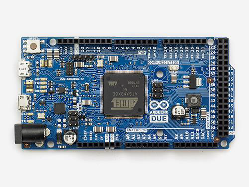
Characteristics of the Arduino Due Board
| Operating volt | CPU speed | Analog in/out | Digital IO/ PWM | EEPROM [KB] | SRAM [KB] | Flash [KB] | USB | UART |
|---|---|---|---|---|---|---|---|---|
| 3.3 Volt | 84 Mhz | 12/2 | 54/12 | - | 96 | 512 | 2 micro | 4 |
Communication
- 4 Hardware UARTs
- 2 I2C
- 1 CAN Interface (Automotive communication protocol)
- 1 SPI
- 1 Interface JTAG (10 pin)
- 1 USB Host (like as Leonardo)
- 1 Programming Port
Unlike most Arduino boards, the Arduino Due board runs at 3.3V. The maximum voltage that the I/O pins can tolerate is 3.3V. Applying voltages higher than 3.3V to any I/O pin could damage the board.
The board contains everything needed to support the microcontroller. You can simply connect it to a computer with a micro-USB cable or power it with an AC-to-DC adapter or battery to get started. The Due is compatible with all Arduino shields that work at 3.3V.
Arduino Zero
The Zero is a simple and powerful 32-bit extension of the platform established by the UNO. The Zero board expands the family by providing increased performance, enabling a variety of project opportunities for devices, and acts as a great educational tool for learning about 32-bit application development.
Important features are −
The Zero applications span from smart IoT devices, wearable technology, high-tech automation, to crazy robotics.
The board is powered by Atmels SAMD21 MCU, which features a 32-bit ARM Cortex® M0+ core.
One of its most important features is Atmels Embedded Debugger (EDBG), which provides a full debug interface without the need for additional hardware, significantly increasing the ease-of-use for software debugging.
EDBG also supports a virtual COM port that can be used for device and bootloader programming.
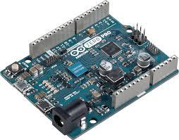
Characteristics of the Arduino Zero board
| Operating volt | CPU speed | Analog in/out | Digital IO/ PWM | EEPROM [KB] | SRAM [KB] | Flash [KB] | USB | UART |
|---|---|---|---|---|---|---|---|---|
| 3.3 Volt | 48 Mhz | 6/1 | 14/10 | - | 32 | 256 | 2 micro | 2 |
Unlike most Arduino and Genuino boards, the Zero runs at 3.3V. The maximum voltage that the I/O pins can tolerate is 3.3V. Applying voltages higher than 3.3V to any I/O pin could damage the board.
The board contains everything needed to support the microcontroller. You can simply connect it to a computer with a micro-USB cable or power it with an AC-to-DC adapter or a battery to get started. The Zero is compatible with all the shields that work at 3.3V.
Arduino - Pulse Width Modulation
Pulse Width Modulation or PWM is a common technique used to vary the width of the pulses in a pulse-train. PWM has many applications such as controlling servos and speed controllers, limiting the effective power of motors and LEDs.
Basic Principle of PWM
Pulse width modulation is basically, a square wave with a varying high and low time. A basic PWM signal is shown in the following figure.
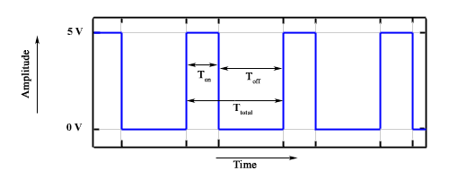
There are various terms associated with PWM −
On-Time − Duration of time signal is high.
Off-Time − Duration of time signal is low.
Period − It is represented as the sum of on-time and off-time of PWM signal.
Duty Cycle − It is represented as the percentage of time signal that remains on during the period of the PWM signal.
Period
As shown in the figure, Ton denotes the on-time and Toff denotes the off-time of signal. Period is the sum of both on and off times and is calculated as shown in the following equation −
$$T_{total} = T_{on}+T_{off}$$Duty Cycle
Duty cycle is calculated as the on-time of the period of time. Using the period calculated above, duty cycle is calculated as −
$$D = \frac{T_{on}}{T_{on}+T_{off}} = \frac{T_{on}}{T_{total}}$$analogWrite() Function
The analogWrite() function writes an analog value (PWM wave) to a pin. It can be used to light a LED at varying brightness or drive a motor at various speeds. After a call of the analogWrite() function, the pin will generate a steady square wave of the specified duty cycle until the next call to analogWrite() or a call to digitalRead() or digitalWrite() on the same pin. The frequency of the PWM signal on most pins is approximately 490 Hz. On the Uno and similar boards, pins 5 and 6 have a frequency of approximately 980 Hz. Pins 3 and 11 on the Leonardo also run at 980 Hz.
On most Arduino boards (those with the ATmega168 or ATmega328), this function works on pins 3, 5, 6, 9, 10, and 11. On the Arduino Mega, it works on pins 2 - 13 and 44 - 46. Older Arduino boards with an ATmega8 only support analogWrite() on pins 9, 10, and 11.
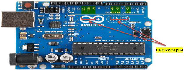
The Arduino Due supports analogWrite() on pins 2 through 13, and pins DAC0 and DAC1. Unlike the PWM pins, DAC0 and DAC1 are Digital to Analog converters, and act as true analog outputs.
You do not need to call pinMode() to set the pin as an output before calling analogWrite().
analogWrite() Function Syntax
analogWrite ( pin , value ) ;
value − the duty cycle: between 0 (always off) and 255 (always on).
Example
int ledPin = 9; // LED connected to digital pin 9
int analogPin = 3; // potentiometer connected to analog pin 3
int val = 0; // variable to store the read value

void setup() {
   pinMode(ledPin, OUTPUT); // sets the pin as output
}

void loop() {
   val = analogRead(analogPin); // read the input pin
   analogWrite(ledPin, (val / 4)); // analogRead values go from 0 to 1023,
      // analogWrite values from 0 to 255
}
Arduino - Random Numbers
To generate random numbers, you can use Arduino random number functions. We have two functions −
- randomSeed(seed)
- random()
randomSeed (seed)
The function randomSeed(seed) resets Arduinos pseudorandom number generator. Although the distribution of the numbers returned by random() is essentially random, the sequence is predictable. You should reset the generator to some random value. If you have an unconnected analog pin, it might pick up random noise from the surrounding environment. These may be radio waves, cosmic rays, electromagnetic interference from cell phones, fluorescent lights and so on.
Example
randomSeed(analogRead(5)); // randomize using noise from analog pin 5
random( )
The random function generates pseudo-random numbers. Following is the syntax.
random( ) Statements Syntax
long random(max) // it generate random numbers from 0 to max
long random(min, max) // it generate random numbers from min to max
Example
long randNumber;

void setup() {
   Serial.begin(9600);
   // if analog input pin 0 is unconnected, random analog
   // noise will cause the call to randomSeed() to generate
   // different seed numbers each time the sketch runs.
   // randomSeed() will then shuffle the random function.
   randomSeed(analogRead(0));
}

void loop() {
   // print a random number from 0 to 299
   Serial.print("random1=");
   randNumber = random(300);
   Serial.println(randNumber); // print a random number from 0to 299
   Serial.print("random2=");
   randNumber = random(10, 20);// print a random number from 10 to 19
   Serial.println (randNumber);
   delay(50);
}
Let us now refresh our knowledge on some of the basic concepts such as bits and bytes.
Bits
A bit is just a binary digit.
The binary system uses two digits, 0 and 1.
Similar to the decimal number system, in which digits of a number do not have the same value, the significance of a bit depends on its position in the binary number. For example, digits in the decimal number 666 are the same, but have different values.
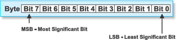
Bytes
A byte consists of eight bits.
If a bit is a digit, it is logical that bytes represent numbers.
All mathematical operations can be performed upon them.
The digits in a byte do not have the same significance either.
The leftmost bit has the greatest value called the Most Significant Bit (MSB).
The rightmost bit has the least value and is therefore, called the Least Significant Bit (LSB).
Since eight zeros and ones of one byte can be combined in 256 different ways, the largest decimal number that can be represented by one byte is 255 (one combination represents a zero).
Arduino - Interrupts
Interrupts stop the current work of Arduino such that some other work can be done.
Suppose you are sitting at home, chatting with someone. Suddenly the telephone rings. You stop chatting, and pick up the telephone to speak to the caller. When you have finished your telephonic conversation, you go back to chatting with the person before the telephone rang.
Similarly, you can think of the main routine as chatting to someone, the telephone ringing causes you to stop chatting. The interrupt service routine is the process of talking on the telephone. When the telephone conversation ends, you then go back to your main routine of chatting. This example explains exactly how an interrupt causes a processor to act.
The main program is running and performing some function in a circuit. However, when an interrupt occurs the main program halts while another routine is carried out. When this routine finishes, the processor goes back to the main routine again.

Important features
Here are some important features about interrupts −
Interrupts can come from various sources. In this case, we are using a hardware interrupt that is triggered by a state change on one of the digital pins.
Most Arduino designs have two hardware interrupts (referred to as "interrupt0" and "interrupt1") hard-wired to digital I/O pins 2 and 3, respectively.
The Arduino Mega has six hardware interrupts including the additional interrupts ("interrupt2" through "interrupt5") on pins 21, 20, 19, and 18.
You can define a routine using a special function called as Interrupt Service Routine (usually known as ISR).
You can define the routine and specify conditions at the rising edge, falling edge or both. At these specific conditions, the interrupt would be serviced.
It is possible to have that function executed automatically, each time an event happens on an input pin.
Types of Interrupts
There are two types of interrupts −
Hardware Interrupts − They occur in response to an external event, such as an external interrupt pin going high or low.
Software Interrupts − They occur in response to an instruction sent in software. The only type of interrupt that the Arduino language supports is the attachInterrupt() function.
Using Interrupts in Arduino
Interrupts are very useful in Arduino programs as it helps in solving timing problems. A good application of an interrupt is reading a rotary encoder or observing a user input. Generally, an ISR should be as short and fast as possible. If your sketch uses multiple ISRs, only one can run at a time. Other interrupts will be executed after the current one finishes in an order that depends on the priority they have.
Typically, global variables are used to pass data between an ISR and the main program. To make sure variables shared between an ISR and the main program are updated correctly, declare them as volatile.
attachInterrupt Statement Syntax
attachInterrupt(digitalPinToInterrupt(pin),ISR,mode);//recommended for arduino board
attachInterrupt(pin, ISR, mode) ; //recommended Arduino Due, Zero only
//argument pin: the pin number
//argument ISR: the ISR to call when the interrupt occurs;
   //this function must take no parameters and return nothing.
   //This function is sometimes referred to as an interrupt service routine.
//argument mode: defines when the interrupt should be triggered.
The following three constants are predefined as valid values −
LOW to trigger the interrupt whenever the pin is low.
CHANGE to trigger the interrupt whenever the pin changes value.
FALLING whenever the pin goes from high to low.
Example
int pin = 2; //define interrupt pin to 2
volatile int state = LOW; // To make sure variables shared between an ISR
//the main program are updated correctly,declare them as volatile.

void setup() {
   pinMode(13, OUTPUT); //set pin 13 as output
   attachInterrupt(digitalPinToInterrupt(pin), blink, CHANGE);
   //interrupt at pin 2 blink ISR when pin to change the value
}
void loop() {
   digitalWrite(13, state); //pin 13 equal the state value
}

void blink() {
   //ISR function
   state = !state; //toggle the state when the interrupt occurs
}
Arduino - Communication
Hundreds of communication protocols have been defined to achieve this data exchange. Each protocol can be categorized into one of the two categories: parallel or serial.
Parallel Communication
Parallel connection between the Arduino and peripherals via input/output ports is the ideal solution for shorter distances up to several meters. However, in other cases when it is necessary to establish communication between two devices for longer distances it is not possible to use parallel connection. Parallel interfaces transfer multiple bits at the same time. They usually require buses of data - transmitting across eight, sixteen, or more wires. Data is transferred in huge, crashing waves of 1s and 0s.
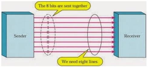
Advantages and Drawbacks of Parallel Communication
Parallel communication certainly has its advantages. It is faster than serial, straightforward, and relatively easy to implement. However, it requires many input/output (I/O) ports and lines. If you have ever had to move a project from a basic Arduino Uno to a Mega, you know that the I/O lines on a microprocessor can be precious and few. Therefore, we prefer serial communication, sacrificing potential speed for pin real estate.
Serial Communication Modules
Today, most Arduino boards are built with several different systems for serial communication as standard equipment.
Which of these systems are used depends on the following factors −
- How many devices the microcontroller has to exchange data with?
- How fast the data exchange has to be?
- What is the distance between these devices?
- Is it necessary to send and receive data simultaneously?
One of the most important things concerning serial communication is the Protocol, which should be strictly observed. It is a set of rules, which must be applied such that the devices can correctly interpret data they mutually exchange. Fortunately, Arduino automatically takes care of this, so that the work of the programmer/user is reduced to simple write (data to be sent) and read (received data).
Types of Serial Communications
Serial communication can be further classified as −
Synchronous − Devices that are synchronized use the same clock and their timing is in synchronization with each other.
Asynchronous − Devices that are asynchronous have their own clocks and are triggered by the output of the previous state.
It is easy to find out if a device is synchronous or not. If the same clock is given to all the connected devices, then they are synchronous. If there is no clock line, it is asynchronous.
For example, UART (Universal Asynchronous Receiver Transmitter) module is asynchronous.
The asynchronous serial protocol has a number of built-in rules. These rules are nothing but mechanisms that help ensure robust and error-free data transfers. These mechanisms, which we get for eschewing the external clock signal, are −
- Synchronization bits
- Data bits
- Parity bits
- Baud rate
Synchronization Bits
The synchronization bits are two or three special bits transferred with each packet of data. They are the start bit and the stop bit(s). True to their name, these bits mark the beginning and the end of a packet respectively.
There is always only one start bit, but the number of stop bits is configurable to either one or two (though it is normally left at one).
The start bit is always indicated by an idle data line going from 1 to 0, while the stop bit(s) will transition back to the idle state by holding the line at 1.
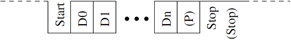
Data Bits
The amount of data in each packet can be set to any size from 5 to 9 bits. Certainly, the standard data size is your basic 8-bit byte, but other sizes have their uses. A 7-bit data packet can be more efficient than 8, especially if you are just transferring 7-bit ASCII characters.
Parity Bits
The user can select whether there should be a parity bit or not, and if yes, whether the parity should be odd or even. The parity bit is 0 if the number of 1s among the data bits is even. Odd parity is just the opposite.
Baud Rate
The term baud rate is used to denote the number of bits transferred per second [bps]. Note that it refers to bits, not bytes. It is usually required by the protocol that each byte is transferred along with several control bits. It means that one byte in serial data stream may consist of 11 bits. For example, if the baud rate is 300 bps then maximum 37 and minimum 27 bytes may be transferred per second.
Arduino UART
The following code will make Arduino send hello world when it starts up.
void setup() {
   Serial.begin(9600); //set up serial library baud rate to 9600
   Serial.println("hello world"); //print hello world
}

void loop() {

}
After the Arduino sketch has been uploaded to Arduino, open the Serial monitor  at the top right section of Arduino IDE.
Type anything into the top box of the Serial Monitor and press send or enter on your keyboard. This will send a series of bytes to the Arduino.
The following code returns whatever it receives as an input.
The following code will make Arduino deliver output depending on the input provided.
void setup() {
   Serial.begin(9600); //set up serial library baud rate to 9600
}

void loop() {
   if(Serial.available()) //if number of bytes (characters) available for reading from {
      serial port
      Serial.print("I received:"); //print I received
      Serial.write(Serial.read()); //send what you read
   }
}
Notice that Serial.print and Serial.println will send back the actual ASCII code, whereas Serial.write will send back the actual text. See ASCII codes for more information.
Arduino - Inter Integrated Circuit
Inter-integrated circuit (I2C) is a system for serial data exchange between the microcontrollers and specialized integrated circuits of a new generation. It is used when the distance between them is short (receiver and transmitter are usually on the same printed board). Connection is established via two conductors. One is used for data transfer and the other is used for synchronization (clock signal).
As seen in the following figure, one device is always a master. It performs addressing of one slave chip before the communication starts. In this way, one microcontroller can communicate with 112 different devices. Baud rate is usually 100 Kb/sec (standard mode) or 10 Kb/sec (slow baud rate mode). Systems with the baud rate of 3.4 Mb/sec have recently appeared. The distance between devices, which communicate over an I2C bus is limited to several meters.
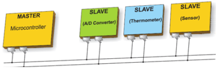
Board I2C Pins
The I2C bus consists of two signals − SCL and SDA. SCL is the clock signal, and SDA is the data signal. The current bus master always generates the clock signal. Some slave devices may force the clock low at times to delay the master sending more data (or to require more time to prepare data before the master attempts to clock it out). This is known as clock stretching.
Following are the pins for different Arduino boards −
- Uno, Pro Mini A4 (SDA), A5 (SCL)
- Mega, Due 20 (SDA), 21 (SCL)
- Leonardo, Yun 2 (SDA), 3 (SCL)
Arduino I2C
We have two modes - master code and slave code - to connect two Arduino boards using I2C. They are −
- Master Transmitter / Slave Receiver
- Master Receiver / Slave Transmitter
Master Transmitter / Slave Receiver
Let us now see what is master transmitter and slave receiver.
Master Transmitter
The following functions are used to initialize the Wire library and join the I2C bus as a master or slave. This is normally called only once.
Wire.begin(address) − Address is the 7-bit slave address in our case as the master is not specified and it will join the bus as a master.
Wire.beginTransmission(address) − Begin a transmission to the I2C slave device with the given address.
Wire.write(value) − Queues bytes for transmission from a master to slave device (in-between calls to beginTransmission() and endTransmission()).
Wire.endTransmission() − Ends a transmission to a slave device that was begun by beginTransmission() and transmits the bytes that were queued by wire.write().
Example
#include <Wire.h> //include wire library

void setup() //this will run only once {
   Wire.begin(); // join i2c bus as master
}

short age = 0;

void loop() {
   Wire.beginTransmission(2);
   // transmit to device #2
   Wire.write("age is = ");
   Wire.write(age); // sends one byte
   Wire.endTransmission(); // stop transmitting
   delay(1000);
}
Slave Receiver
The following functions are used −
Wire.begin(address) − Address is the 7-bit slave address.
Wire.onReceive(received data handler) − Function to be called when a slave device receives data from the master.
Wire.available() − Returns the number of bytes available for retrieval with Wire.read().This should be called inside the Wire.onReceive() handler.
Example
#include <Wire.h> //include wire library

void setup() {  //this will run only once
   Wire.begin(2); // join i2c bus with address #2
   Wire.onReceive(receiveEvent); // call receiveEvent when the master send any thing
   Serial.begin(9600); // start serial for output to print what we receive
}

void loop() {
   delay(250);
}

//-----this function will execute whenever data is received from master-----//

void receiveEvent(int howMany) {
   while (Wire.available()>1) // loop through all but the last {
      char c = Wire.read(); // receive byte as a character
      Serial.print(c); // print the character
   }
}
Master Receiver / Slave Transmitter
Let us now see what is master receiver and slave transmitter.
Master Receiver
The Master, is programmed to request, and then read bytes of data that are sent from the uniquely addressed Slave Arduino.
The following function is used −
Wire.requestFrom(address,number of bytes) − Used by the master to request bytes from a slave device. The bytes may then be retrieved with the functions wire.available() and wire.read() functions.
Example
#include <Wire.h> //include wire library void setup() {
   Wire.begin(); // join i2c bus (address optional for master)
   Serial.begin(9600); // start serial for output
}

void loop() {
   Wire.requestFrom(2, 1); // request 1 bytes from slave device #2
   while (Wire.available()) // slave may send less than requested {
      char c = Wire.read(); // receive a byte as character
      Serial.print(c); // print the character
   }
   delay(500);
}
Slave Transmitter
The following function is used.
Wire.onRequest(handler) − A function is called when a master requests data from this slave device.
Example
#include <Wire.h>

void setup() {
   Wire.begin(2); // join i2c bus with address #2
   Wire.onRequest(requestEvent); // register event
}

Byte x = 0;

void loop() {
   delay(100);
}

// function that executes whenever data is requested by master
// this function is registered as an event, see setup()

void requestEvent() {
   Wire.write(x); // respond with message of 1 bytes as expected by master
   x++;
}
Arduino - Serial Peripheral Interface
A Serial Peripheral Interface (SPI) bus is a system for serial communication, which uses up to four conductors, commonly three. One conductor is used for data receiving, one for data sending, one for synchronization and one alternatively for selecting a device to communicate with. It is a full duplex connection, which means that the data is sent and received simultaneously. The maximum baud rate is higher than that in the I2C communication system.
Board SPI Pins
SPI uses the following four wires −
SCK − This is the serial clock driven by the master.
MOSI − This is the master output / slave input driven by the master.
MISO − This is the master input / slave output driven by the master.
SS − This is the slave-selection wire.
The following functions are used. You have to include the SPI.h.
SPI.begin() − Initializes the SPI bus by setting SCK, MOSI, and SS to outputs, pulling SCK and MOSI low, and SS high.
SPI.setClockDivider(divider) − To set the SPI clock divider relative to the system clock. On AVR based boards, the dividers available are 2, 4, 8, 16, 32, 64 or 128. The default setting is SPI_CLOCK_DIV4, which sets the SPI clock to one-quarter of the frequency of the system clock (5 Mhz for the boards at 20 MHz).
Divider − It could be (SPI_CLOCK_DIV2, SPI_CLOCK_DIV4, SPI_CLOCK_DIV8, SPI_CLOCK_DIV16, SPI_CLOCK_DIV32, SPI_CLOCK_DIV64, SPI_CLOCK_DIV128).
SPI.transfer(val) − SPI transfer is based on a simultaneous send and receive: the received data is returned in receivedVal.
SPI.beginTransaction(SPISettings(speedMaximum, dataOrder, dataMode)) − speedMaximum is the clock, dataOrder(MSBFIRST or LSBFIRST), dataMode(SPI_MODE0, SPI_MODE1, SPI_MODE2, or SPI_MODE3).
We have four modes of operation in SPI as follows −
Mode 0 (the default) − Clock is normally low (CPOL = 0), and the data is sampled on the transition from low to high (leading edge) (CPHA = 0).
Mode 1 − Clock is normally low (CPOL = 0), and the data is sampled on the transition from high to low (trailing edge) (CPHA = 1).
Mode 2 − Clock is normally high (CPOL = 1), and the data is sampled on the transition from high to low (leading edge) (CPHA = 0).
Mode 3 − Clock is normally high (CPOL = 1), and the data is sampled on the transition from low to high (trailing edge) (CPHA = 1).
SPI.attachInterrupt(handler) − Function to be called when a slave device receives data from the master.
Now, we will connect two Arduino UNO boards together; one as a master and the other as a slave.
- (SS) : pin 10
- (MOSI) : pin 11
- (MISO) : pin 12
- (SCK) : pin 13
The ground is common. Following is the diagrammatic representation of the connection between both the boards −
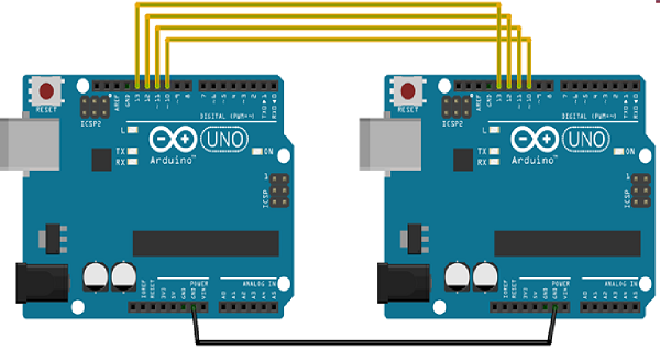
Let us see examples of SPI as Master and SPI as Slave.
SPI as MASTER
Example
#include <SPI.h>

void setup (void) {
   Serial.begin(115200); //set baud rate to 115200 for usart
   digitalWrite(SS, HIGH); // disable Slave Select
   SPI.begin ();
   SPI.setClockDivider(SPI_CLOCK_DIV8);//divide the clock by 8
}

void loop (void) {
   char c;
   digitalWrite(SS, LOW); // enable Slave Select
   // send test string
   for (const char * p = "Hello, world!\r" ; c = *p; p++) {
      SPI.transfer (c);
      Serial.print(c);
   }
   digitalWrite(SS, HIGH); // disable Slave Select
   delay(2000);
}
SPI as SLAVE
Example
#include <SPI.h>
char buff [50];
volatile byte indx;
volatile boolean process;

void setup (void) {
   Serial.begin (115200);
   pinMode(MISO, OUTPUT); // have to send on master in so it set as output
   SPCR |= _BV(SPE); // turn on SPI in slave mode
   indx = 0; // buffer empty
   process = false;
   SPI.attachInterrupt(); // turn on interrupt
}
ISR (SPI_STC_vect) // SPI interrupt routine {
   byte c = SPDR; // read byte from SPI Data Register
   if (indx < sizeof buff) {
      buff [indx++] = c; // save data in the next index in the array buff
      if (c == '\r') //check for the end of the word
      process = true;
   }
}

void loop (void) {
   if (process) {
      process = false; //reset the process
      Serial.println (buff); //print the array on serial monitor
      indx= 0; //reset button to zero
   }
}
Arduino - Blinking LED
LEDs are small, powerful lights that are used in many different applications. To start, we will work on blinking an LED, the Hello World of microcontrollers. It is as simple as turning a light on and off. Establishing this important baseline will give you a solid foundation as we work towards experiments that are more complex.
Components Required
You will need the following components −
- 1 × Breadboard
- 1 × Arduino Uno R3
- 1 × LED
- 1 × 330 Resistor
- 2 × Jumper
Procedure
Follow the circuit diagram and hook up the components on the breadboard as shown in the image given below.
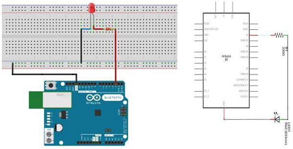
Note − To find out the polarity of an LED, look at it closely. The shorter of the two legs, towards the flat edge of the bulb indicates the negative terminal.
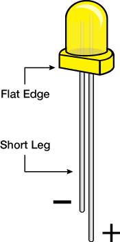
Components like resistors need to have their terminals bent into 90 angles in order to fit the breadboard sockets properly. You can also cut the terminals shorter.
Sketch
Open the Arduino IDE software on your computer. Coding in the Arduino language will control your circuit. Open the new sketch File by clicking New.
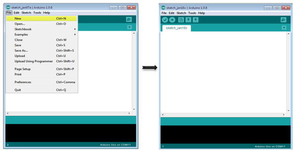
Arduino Code
/*
   Blink
   Turns on an LED on for one second, then off for one second, repeatedly.
*/

// the setup function runs once when you press reset or power the board

void setup() {  // initialize digital pin 13 as an output.
   pinMode(2, OUTPUT);
}

// the loop function runs over and over again forever

void loop() {
   digitalWrite(2, HIGH); // turn the LED on (HIGH is the voltage level)
   delay(1000); // wait for a second
   digitalWrite(2, LOW); // turn the LED off by making the voltage LOW
   delay(1000); // wait for a second
}
Code to Note
pinMode(2, OUTPUT) − Before you can use one of Arduinos pins, you need to tell Arduino Uno R3 whether it is an INPUT or OUTPUT. We use a built-in function called pinMode() to do this.
digitalWrite(2, HIGH) − When you are using a pin as an OUTPUT, you can command it to be HIGH (output 5 volts), or LOW (output 0 volts).
Result
You should see your LED turn on and off. If the required output is not seen, make sure you have assembled the circuit correctly, and verified and uploaded the code to your board.
Arduino - Fading LED
This example demonstrates the use of the analogWrite() function in fading an LED off. AnalogWrite uses pulse width modulation (PWM), turning a digital pin on and off very quickly with different ratios between on and off, to create a fading effect.
Components Required
You will need the following components −
- 1 × Breadboard
- 1 × Arduino Uno R3
- 1 × LED
- 1 × 330 Resistor
- 2 × Jumper
Procedure
Follow the circuit diagram and hook up the components on the breadboard as shown in the image given below.
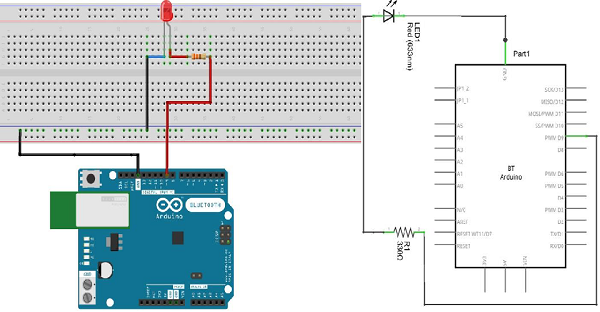
Note − To find out the polarity of an LED, look at it closely. The shorter of the two legs, towards the flat edge of the bulb indicates the negative terminal.
Components like resistors need to have their terminals bent into 90 angles in order to fit the breadboard sockets properly. You can also cut the terminals shorter.
Sketch
Open the Arduino IDE software on your computer. Coding in the Arduino language will control your circuit. Open the new sketch File by clicking New.
Arduino Code
/*
   Fade
   This example shows how to fade an LED on pin 9 using the analogWrite() function.

   The analogWrite() function uses PWM, so if you want to change the pin you're using, be
   sure to use another PWM capable pin. On most Arduino, the PWM pins are identified with
   a "~" sign, like ~3, ~5, ~6, ~9, ~10 and ~11.
*/

int led = 9; // the PWM pin the LED is attached to
int brightness = 0; // how bright the LED is
int fadeAmount = 5; // how many points to fade the LED by
// the setup routine runs once when you press reset:

void setup() {
   // declare pin 9 to be an output:
   pinMode(led, OUTPUT);
}

// the loop routine runs over and over again forever:

void loop() {
   // set the brightness of pin 9:
   analogWrite(led, brightness);
   // change the brightness for next time through the loop:
   brightness = brightness + fadeAmount;
   // reverse the direction of the fading at the ends of the fade:
   if (brightness == 0 || brightness == 255) {
      fadeAmount = -fadeAmount ;
   }
   // wait for 30 milliseconds to see the dimming effect
   delay(300);
}
Code to Note
After declaring pin 9 as your LED pin, there is nothing to do in the setup() function of your code. The analogWrite() function that you will be using in the main loop of your code requires two arguments: One, telling the function which pin to write to and the other indicating what PWM value to write.
In order to fade the LED off and on, gradually increase the PWM values from 0 (all the way off) to 255 (all the way on), and then back to 0, to complete the cycle. In the sketch given above, the PWM value is set using a variable called brightness. Each time through the loop, it increases by the value of the variable fadeAmount.
If brightness is at either extreme of its value (either 0 or 255), then fadeAmount is changed to its negative. In other words, if fadeAmount is 5, then it is set to -5. If it is -5, then it is set to 5. The next time through the loop, this change causes brightness to change direction as well.
analogWrite() can change the PWM value very fast, so the delay at the end of the sketch controls the speed of the fade. Try changing the value of the delay and see how it changes the fading effect.
Result
You should see your LED brightness change gradually.
Arduino - Reading Analog Voltage
This example will show you how to read an analog input on analog pin 0. The input is converted from analogRead() into voltage, and printed out to the serial monitor of the Arduino Software (IDE).
Components Required
You will need the following components −
- 1 × Breadboard
- 1 × Arduino Uno R3
- 1 × 5K variable resistor (potentiometer)
- 2 × Jumper
Procedure
Follow the circuit diagram and hook up the components on the breadboard as shown in the image given below.

Potentiometer
A potentiometer (or pot) is a simple electro-mechanical transducer. It converts rotary or linear motion from the input operator into a change of resistance. This change is (or can be) used to control anything from the volume of a hi-fi system to the direction of a huge container ship.
The pot as we know it was originally known as a rheostat (essentially a variable wirewound resistor). The variety of available pots is now quite astonishing, and it can be very difficult for the beginner (in particular) to work out which type is suitable for a given task. A few different pot types, which can all be used for the same task makes the job harder.
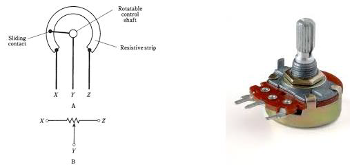
The image on the left shows the standard schematic symbol of a pot. The image on the right is the potentiometer.
Sketch
Open the Arduino IDE software on your computer. Coding in the Arduino language will control your circuit. Open a new sketch File by clicking New.
Arduino Code
/*
   ReadAnalogVoltage
   Reads an analog input on pin 0, converts it to voltage,
   and prints the result to the serial monitor.
   Graphical representation is available using serial plotter (Tools > Serial Plotter menu)
   Attach the center pin of a potentiometer to pin A0, and the outside pins to +5V and ground.
*/

// the setup routine runs once when you press reset:

void setup() {
   // initialize serial communication at 9600 bits per second:
   Serial.begin(9600);
}

// the loop routine runs over and over again forever:

void loop() {
   // read the input on analog pin 0:
   int sensorValue = analogRead(A0);
   // Convert the analog reading (which goes from 0 - 1023) to a voltage (0 - 5V):
   float voltage = sensorValue * (5.0 / 1023.0);
   // print out the value you read:
   Serial.println(voltage);
}
Code to Note
In the program or sketch given below, the first thing that you do in the setup function is begin serial communications, at 9600 bits per second, between your board and your computer with the line −
Serial.begin(9600);
In the main loop of your code, you need to establish a variable to store the resistance value (which will be between 0 and 1023, perfect for an int datatype) coming from your potentiometer −
int sensorValue = analogRead(A0);
To change the values from 0-1023 to a range that corresponds to the voltage, the pin is reading, you need to create another variable, a float, and do a little calculation. To scale the numbers between 0.0 and 5.0, divide 5.0 by 1023.0 and multiply that by sensorValue −
float voltage= sensorValue * (5.0 / 1023.0);
Finally, you need to print this information to your serial window. You can do this with the command Serial.println() in your last line of code −
Serial.println(voltage)
Now, open Serial Monitor in the Arduino IDE by clicking the icon on the right side of the top green bar or pressing Ctrl+Shift+M.
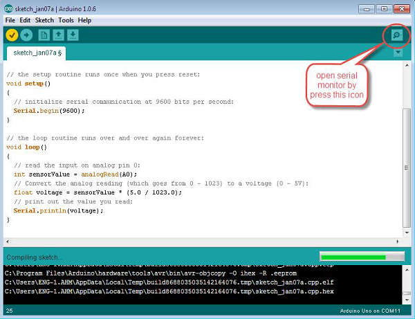
Result
You will see a steady stream of numbers ranging from 0.0 - 5.0. As you turn the pot, the values will change, corresponding to the voltage at pin A0.
Arduino - LED Bar Graph
This example shows you how to read an analog input at analog pin 0, convert the values from analogRead() into voltage, and print it out to the serial monitor of the Arduino Software (IDE).
Components Required
You will need the following components −
- 1 × Breadboard
- 1 × Arduino Uno R3
- 1 × 5k ohm variable resistor (potentiometer)
- 2 × Jumper
- 8 × LED or you can use (LED bar graph display as shown in the image below)
Procedure
Follow the circuit diagram and hook up the components on the breadboard as shown in the image given below.
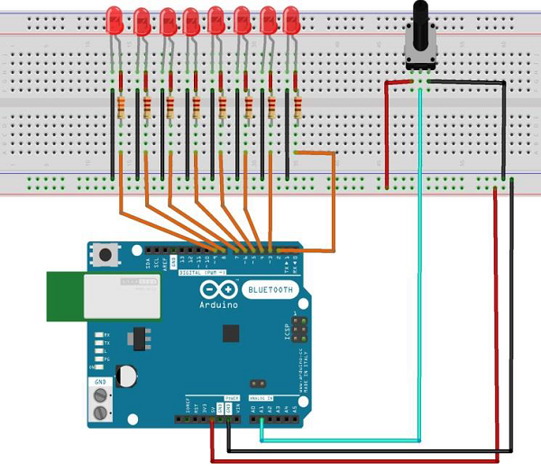
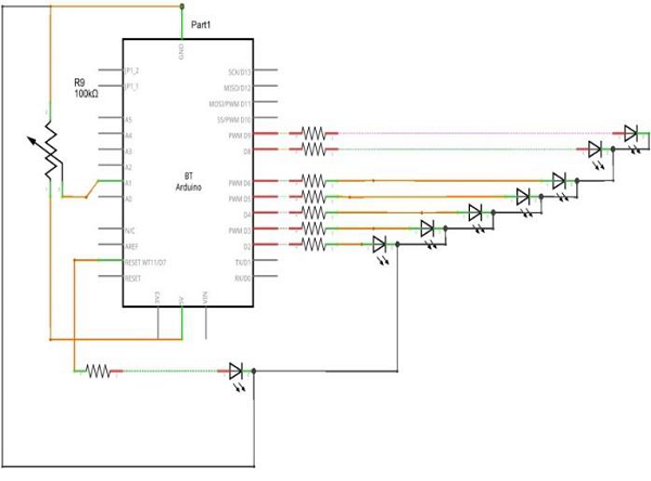
Sketch
Open the Arduino IDE software on your computer. Coding in the Arduino language will control your circuit. Open a new sketch File by clicking New.
10 Segment LED Bar Graph
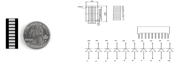
These 10-segment bar graph LEDs have many uses. With a compact footprint, simple hookup, they are easy for prototype or finished products. Essentially, they are 10 individual blue LEDs housed together, each with an individual anode and cathode connection.
They are also available in yellow, red, and green colors.
Note − The pin out on these bar graphs may vary from what is listed on the datasheet. Rotating the device 180 degrees will correct the change, making pin 11 the first pin in line.
Arduino Code
/*
   LED bar graph
   Turns on a series of LEDs based on the value of an analog sensor.
   This is a simple way to make a bar graph display.
   Though this graph uses 8LEDs, you can use any number by
      changing the LED count and the pins in the array.
   This method can be used to control any series of digital
      outputs that depends on an analog input.
*/

// these constants won't change:
const int analogPin = A0; // the pin that the potentiometer is attached to
const int ledCount = 8; // the number of LEDs in the bar graph
int ledPins[] = {2, 3, 4, 5, 6, 7, 8, 9}; // an array of pin numbers to which LEDs are attached

void setup() {
   // loop over the pin array and set them all to output:
   for (int thisLed = 0; thisLed < ledCount; thisLed++) {
      pinMode(ledPins[thisLed], OUTPUT);
   }
}

void loop() {
   // read the potentiometer:
   int sensorReading = analogRead(analogPin);
   // map the result to a range from 0 to the number of LEDs:
   int ledLevel = map(sensorReading, 0, 1023, 0, ledCount);
   // loop over the LED array:
   for (int thisLed = 0; thisLed < ledCount; thisLed++) {
      // if the array element's index is less than ledLevel,
      // turn the pin for this element on:
      if (thisLed < ledLevel) {
         digitalWrite(ledPins[thisLed], HIGH);
      }else { // turn off all pins higher than the ledLevel:
         digitalWrite(ledPins[thisLed], LOW);
      }
   }
}
Code to Note
The sketch works like this: first, you read the input. You map the input value to the output range, in this case ten LEDs. Then you set up a for-loop to iterate over the outputs. If the output's number in the series is lower than the mapped input range, you turn it on. If not, you turn it off.
Result
You will see the LED turn ON one by one when the value of analog reading increases and turn OFF one by one while the reading is decreasing.
Arduino - Keyboard Logout
This example uses the Keyboard library to log you out of your user session on your computer when pin 2 on the ARDUINO UNO is pulled to ground. The sketch simulates the keypress in sequence of two or three keys at the same time and after a short delay, it releases them.
Warning − When you use the Keyboard.print() command, Arduino takes over your computer's keyboard. To ensure you do not lose control of your computer while running a sketch with this function, set up a reliable control system before you call Keyboard.print(). This sketch is designed to only send a Keyboard command after a pin has been pulled to ground.
Components Required
You will need the following components −
- 1 × Breadboard
- 1 × Arduino Leonardo, Micro, or Due board
- 1 × pushbutton
- 1 × Jumper
Procedure
Follow the circuit diagram and hook up the components on the breadboard as shown in the image below.
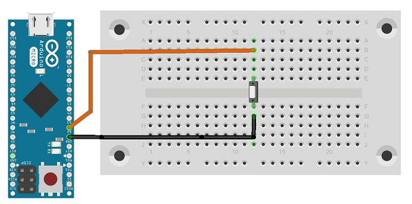
Sketch
Open the Arduino IDE software on your computer. Coding in the Arduino language will control your circuit. Open a new sketch File by clicking New.
For this example, you need to use Arduino IDE 1.6.7
Note − You must include the keyboard library in your Arduino library file. Copy and paste the keypad library file inside the file with the name libraries (highlighted) as shown in the following screenshot.
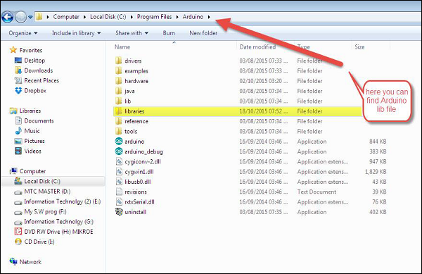
Arduino Code
/*
   Keyboard logout
   This sketch demonstrates the Keyboard library.
   When you connect pin 2 to ground, it performs a logout.
   It uses keyboard combinations to do this, as follows:
   On Windows, CTRL-ALT-DEL followed by ALT-l
   On Ubuntu, CTRL-ALT-DEL, and ENTER
   On OSX, CMD-SHIFT-q
   To wake: Spacebar.
   Circuit:
   * Arduino Leonardo or Micro
   * wire to connect D2 to ground.
*/

#define OSX 0
#define WINDOWS 1
#define UBUNTU 2

#include "Keyboard.h"

// change this to match your platform:
int platform = WINDOWS;

void setup() {
   // make pin 2 an input and turn on the
   // pullup resistor so it goes high unless
   // connected to ground:

   pinMode(2, INPUT_PULLUP);
   Keyboard.begin();
}

void loop() {
   while (digitalRead(2) == HIGH) {
      // do nothing until pin 2 goes low
      delay(500);
   }

   delay(1000);

   switch (platform) {
      case OSX:
      Keyboard.press(KEY_LEFT_GUI);

      // Shift-Q logs out:
      Keyboard.press(KEY_LEFT_SHIFT);
      Keyboard.press('Q');
      delay(100);

      // enter:
      Keyboard.write(KEY_RETURN);
      break;

      case WINDOWS:
      // CTRL-ALT-DEL:
      Keyboard.press(KEY_LEFT_CTRL);
      Keyboard.press(KEY_LEFT_ALT);
      Keyboard.press(KEY_DELETE);
      delay(100);
      Keyboard.releaseAll();

      //ALT-l:
      delay(2000);
      Keyboard.press(KEY_LEFT_ALT);
      Keyboard.press('l');
      Keyboard.releaseAll();
      break;

      case UBUNTU:
      // CTRL-ALT-DEL:
      Keyboard.press(KEY_LEFT_CTRL);
      Keyboard.press(KEY_LEFT_ALT);
      Keyboard.press(KEY_DELETE);

      delay(1000);
      Keyboard.releaseAll();

      // Enter to confirm logout:
      Keyboard.write(KEY_RETURN);
      break;
   }

   // do nothing:
   while (true);
}

Keyboard.releaseAll();

   // enter:
      Keyboard.write(KEY_RETURN);
      break;
      case WINDOWS:

   // CTRL-ALT-DEL:
      Keyboard.press(KEY_LEFT_CTRL);
      Keyboard.press(KEY_LEFT_ALT);
      Keyboard.press(KEY_DELETE);
      delay(100);
      Keyboard.releaseAll();

   //ALT-l:
      delay(2000);
      Keyboard.press(KEY_LEFT_ALT);
      Keyboard.press('l');
      Keyboard.releaseAll();
      break;

   case UBUNTU:
      // CTRL-ALT-DEL:
      Keyboard.press(KEY_LEFT_CTRL);
      Keyboard.press(KEY_LEFT_ALT);
      Keyboard.press(KEY_DELETE);
      delay(1000);
      Keyboard.releaseAll();

      // Enter to confirm logout:
      Keyboard.write(KEY_RETURN);
      break;
   }

// do nothing:
   while (true);
}
Code to Note
Before you upload the program to your board, make sure you assign the correct OS you are currently using to the platform variable.
While the sketch is running, pressing the button will connect pin 2 to the ground and the board will send the logout sequence to the USB connected PC.
Result
When you connect pin 2 to the ground, it performs a logout operation.
It uses the following keyboard combinations to logout −
On Windows, CTRL-ALT-DEL followed by ALT-l
On Ubuntu, CTRL-ALT-DEL, and ENTER
On OSX, CMD-SHIFT-q
Arduino - Keyboard Message
In this example, when the button is pressed, a text string is sent to the computer as keyboard input. The string reports the number of times the button is pressed. Once you have the Leonardo programmed and wired up, open your favorite text editor to see the results.
Warning − When you use the Keyboard.print() command, the Arduino takes over your computer's keyboard. To ensure you do not lose control of your computer while running a sketch with this function, set up a reliable control system before you call Keyboard.print(). This sketch includes a pushbutton to toggle the keyboard, so that it only runs after the button is pressed.
Components Required
You will need the following components −
- 1 × Breadboard
- 1 × Arduino Leonardo, Micro, or Due board
- 1 × momentary pushbutton
- 1 × 10k ohm resistor
Procedure
Follow the circuit diagram and hook up the components on the breadboard as shown in the image given below.
Sketch
Open the Arduino IDE software on your computer. Coding in the Arduino language will control your circuit. Open a new sketch File by clicking New.
Arduino Code
/*
   Keyboard Message test For the Arduino Leonardo and Micro,
      Sends a text string when a button is pressed.
   The circuit:
   * pushbutton attached from pin 4 to +5V
   * 10-kilohm resistor attached from pin 4 to ground
*/

#include "Keyboard.h"
const int buttonPin = 4; // input pin for pushbutton
int previousButtonState = HIGH; // for checking the state of a pushButton
int counter = 0; // button push counter

void setup() {
   pinMode(buttonPin, INPUT); // make the pushButton pin an input:
   Keyboard.begin(); // initialize control over the keyboard:
}

void loop() {
   int buttonState = digitalRead(buttonPin); // read the pushbutton:
   if ((buttonState != previousButtonState)&& (buttonState == HIGH)) // and it's currently pressed: {
      // increment the button counter
      counter++;
      // type out a message
      Keyboard.print("You pressed the button ");
      Keyboard.print(counter);
      Keyboard.println(" times.");
   }
   // save the current button state for comparison next time:
   previousButtonState = buttonState;
}
Code to Note
Attach one terminal of the pushbutton to pin 4 on Arduino. Attach the other pin to 5V. Use the resistor as a pull-down, providing a reference to the ground, by attaching it from pin 4 to the ground.
Once you have programmed your board, unplug the USB cable, open a text editor and put the text cursor in the typing area. Connect the board to your computer through USB again and press the button to write in the document.
Result
By using any text editor, it will display the text sent via Arduino.
Arduino - Mouse Button Control
Using the Mouse library, you can control a computer's onscreen cursor with an Arduino Leonardo, Micro, or Due.
This particular example uses five pushbuttons to move the onscreen cursor. Four of the buttons are directional (up, down, left, right) and one is for a left mouse click. Cursor movement from Arduino is always relative. Every time an input is read, the cursor's position is updated relative to its current position.
Whenever one of the directional buttons is pressed, Arduino will move the mouse, mapping a HIGH input to a range of 5 in the appropriate direction.
The fifth button is for controlling a left-click from the mouse. When the button is released, the computer will recognize the event.
Components Required
You will need the following components −
- 1 × Breadboard
- 1 × Arduino Leonardo, Micro or Due board
- 5 × 10k ohm resistor
- 5 × momentary pushbuttons
Procedure
Follow the circuit diagram and hook up the components on the breadboard as shown in the image below.
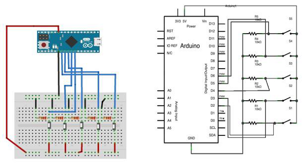
Sketch
Open the Arduino IDE software on your computer. Coding in the Arduino language will control your circuit. Open a new sketch File by clicking New.
For this example, you need to use Arduino IDE 1.6.7
Arduino Code
/*
   Button Mouse Control
   For Leonardo and Due boards only .Controls the mouse from
   five pushbuttons on an Arduino Leonardo, Micro or Due.
   Hardware:
   * 5 pushbuttons attached to D2, D3, D4, D5, D6
   The mouse movement is always relative. This sketch reads
   four pushbuttons, and uses them to set the movement of the mouse.
   WARNING: When you use the Mouse.move() command, the Arduino takes
   over your mouse! Make sure you have control before you use the mouse commands.
*/

#include "Mouse.h"
// set pin numbers for the five buttons:
const int upButton = 2;
const int downButton = 3;
const int leftButton = 4;
const int rightButton = 5;
const int mouseButton = 6;
int range = 5; // output range of X or Y movement; affects movement speed
int responseDelay = 10; // response delay of the mouse, in ms

void setup() {
   // initialize the buttons' inputs:
   pinMode(upButton, INPUT);
   pinMode(downButton, INPUT);
   pinMode(leftButton, INPUT);
   pinMode(rightButton, INPUT);
   pinMode(mouseButton, INPUT);
   // initialize mouse control:
   Mouse.begin();
}

void loop() {
   // read the buttons:
   int upState = digitalRead(upButton);
   int downState = digitalRead(downButton);
   int rightState = digitalRead(rightButton);
   int leftState = digitalRead(leftButton);
   int clickState = digitalRead(mouseButton);
   // calculate the movement distance based on the button states:
   int xDistance = (leftState - rightState) * range;
   int yDistance = (upState - downState) * range;
   // if X or Y is non-zero, move:
   if ((xDistance != 0) || (yDistance != 0)) {
      Mouse.move(xDistance, yDistance, 0);
   }

   // if the mouse button is pressed:
   if (clickState == HIGH) {
      // if the mouse is not pressed, press it:
      if (!Mouse.isPressed(MOUSE_LEFT)) {
         Mouse.press(MOUSE_LEFT);
      }
   } else {                           // else the mouse button is not pressed:
      // if the mouse is pressed, release it:
      if (Mouse.isPressed(MOUSE_LEFT)) {
         Mouse.release(MOUSE_LEFT);
      }
   }
   // a delay so the mouse does not move too fast:
   delay(responseDelay);
}
Code to Note
Connect your board to your computer with a micro-USB cable. The buttons are connected to digital inputs from pins 2 to 6. Make sure you use 10k pull-down resistors.
Arduino - Keyboard Serial
This example listens for a byte coming from the serial port. When received, the board sends a keystroke back to the computer. The sent keystroke is one higher than what is received, so if you send an "a" from the serial monitor, you will receive a "b" from the board connected to the computer. A "1" will return a "2" and so on.
Warning − When you use the Keyboard.print() command, the Leonardo, Micro or Due board takes over your computer's keyboard. To ensure you do not lose control of your computer while running a sketch with this function, set up a reliable control system before you call Keyboard.print(). This sketch is designed to only send a Keyboard command after the board has received a byte over the serial port.
Components Required
You will need the following components −
- 1 × Arduino Leonardo, Micro, or Due board
Procedure
Just connect your board to the computer using USB cable.
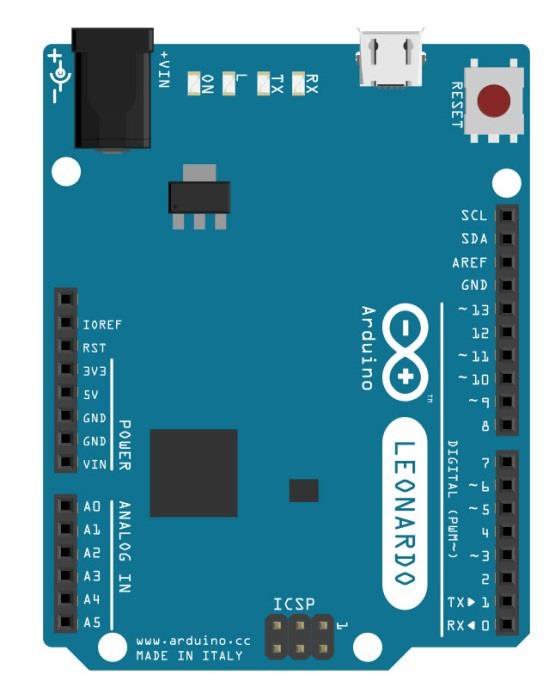
Sketch
Open the Arduino IDE software on your computer. Coding in the Arduino language will control your circuit. Open a new sketch File by clicking New.
Notes − You must include the keypad library in your Arduino library file. Copy and paste the keypad library file inside the file with the name libraries highlighted with yellow color.
Arduino Code
/*
   Keyboard test
   For the Arduino Leonardo, Micro or Due Reads
      a byte from the serial port, sends a keystroke back.
   The sent keystroke is one higher than what's received, e.g. if you send a, you get b, send
      A you get B, and so forth.
   The circuit:
   * none
*/

#include "Keyboard.h"

void setup() {
   // open the serial port:
   Serial.begin(9600);
   // initialize control over the keyboard:
   Keyboard.begin();
}

void loop() {
   // check for incoming serial data:
   if (Serial.available() > 0) {
      // read incoming serial data:
      char inChar = Serial.read();
      // Type the next ASCII value from what you received:
      Keyboard.write(inChar + 1);
   }
}
Code to Note
Once programed, open your serial monitor and send a byte. The board will reply with a keystroke, that is one number higher.
Result
The board will reply with a keystroke that is one number higher on Arduino IDE serial monitor when you send a byte.
Arduino - Humidity Sensor
In this section, we will learn how to interface our Arduino board with different sensors. We will discuss the following sensors −
- Humidity sensor (DHT22)
- Temperature sensor (LM35)
- Water detector sensor (Simple Water Trigger)
- PIR SENSOR
- ULTRASONIC SENSOR
- GPS
Humidity Sensor (DHT22)
The DHT-22 (also named as AM2302) is a digital-output, relative humidity, and temperature sensor. It uses a capacitive humidity sensor and a thermistor to measure the surrounding air, and sends a digital signal on the data pin.
In this example, you will learn how to use this sensor with Arduino UNO. The room temperature and humidity will be printed to the serial monitor.
The DHT-22 Sensor
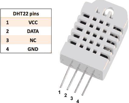
The connections are simple. The first pin on the left to 3-5V power, the second pin to the data input pin and the right-most pin to the ground.
Technical Details
Power − 3-5V
Max Current − 2.5mA
Humidity − 0-100%, 2-5% accuracy
Temperature − 40 to 80C, 0.5C accuracy
Components Required
You will need the following components −
- 1 × Breadboard
- 1 × Arduino Uno R3
- 1 × DHT22
- 1 × 10K ohm resistor
Procedure
Follow the circuit diagram and hook up the components on the breadboard as shown in the image below.
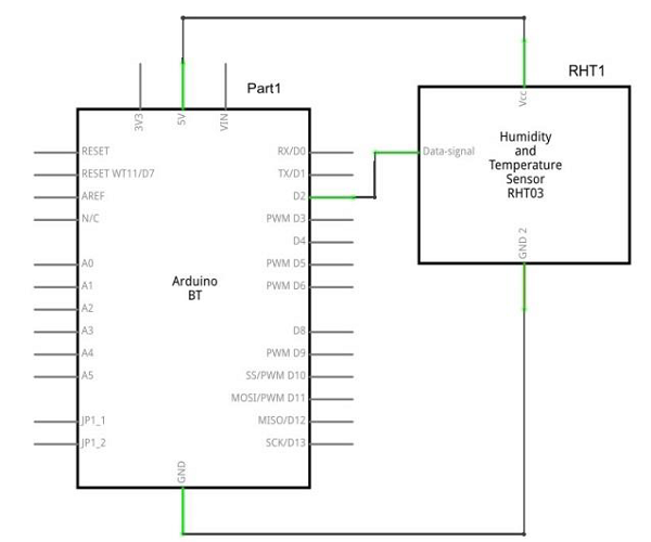
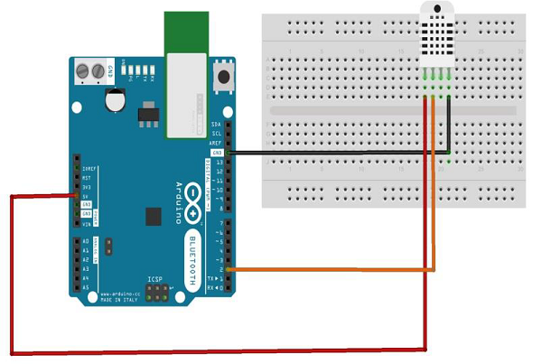
Sketch
Open the Arduino IDE software on your computer. Coding in the Arduino language will control your circuit. Open a new sketch File by clicking New.
Arduino Code
// Example testing sketch for various DHT humidity/temperature sensors

#include "DHT.h"
#define DHTPIN 2 // what digital pin we're connected to
// Uncomment whatever type you're using!
//#define DHTTYPE DHT11 // DHT 11
#define DHTTYPE DHT22 // DHT 22 (AM2302), AM2321
//#define DHTTYPE DHT21 // DHT 21 (AM2301)
// Connect pin 1 (on the left) of the sensor to +5V
// NOTE: If using a board with 3.3V logic like an Arduino Due connect pin 1
// to 3.3V instead of 5V!
// Connect pin 2 of the sensor to whatever your DHTPIN is
// Connect pin 4 (on the right) of the sensor to GROUND
// Connect a 10K resistor from pin 2 (data) to pin 1 (power) of the sensor
// Initialize DHT sensor.
// Note that older versions of this library took an optional third parameter to
// tweak the timings for faster processors. This parameter is no longer needed
// as the current DHT reading algorithm adjusts itself to work on faster procs.
DHT dht(DHTPIN, DHTTYPE);

void setup() {
   Serial.begin(9600);
   Serial.println("DHTxx test!");
   dht.begin();
}

void loop() {
   delay(2000); // Wait a few seconds between measurements
   float h = dht.readHumidity();
   // Reading temperature or humidity takes about 250 milliseconds!
   float t = dht.readTemperature();
   // Read temperature as Celsius (the default)
   float f = dht.readTemperature(true);
   // Read temperature as Fahrenheit (isFahrenheit = true)
   // Check if any reads failed and exit early (to try again).
   if (isnan(h) || isnan(t) || isnan(f)) {
      Serial.println("Failed to read from DHT sensor!");
      return;
   }

   // Compute heat index in Fahrenheit (the default)
   float hif = dht.computeHeatIndex(f, h);
   // Compute heat index in Celsius (isFahreheit = false)
   float hic = dht.computeHeatIndex(t, h, false);
   Serial.print ("Humidity: ");
   Serial.print (h);
   Serial.print (" %\t");
   Serial.print ("Temperature: ");
   Serial.print (t);
   Serial.print (" *C ");
   Serial.print (f);
   Serial.print (" *F\t");
   Serial.print ("Heat index: ");
   Serial.print (hic);
   Serial.print (" *C ");
   Serial.print (hif);
   Serial.println (" *F");
}
Code to Note
DHT22 sensor has four terminals (Vcc, DATA, NC, GND), which are connected to the board as follows −
- DATA pin to Arduino pin number 2
- Vcc pin to 5 volt of Arduino board
- GND pin to the ground of Arduino board
- We need to connect 10k ohm resistor (pull up resistor) between the DATA and the Vcc pin
Once hardware connections are done, you need to add DHT22 library to your Arduino library file as described earlier.
Result
You will see the temperature and humidity display on serial port monitor which is updated every 2 seconds.
Arduino - Temperature Sensor
The Temperature Sensor LM35 series are precision integrated-circuit temperature devices with an output voltage linearly proportional to the Centigrade temperature.
The LM35 device has an advantage over linear temperature sensors calibrated in Kelvin, as the user is not required to subtract a large constant voltage from the output to obtain convenient Centigrade scaling. The LM35 device does not require any external calibration or trimming to provide typical accuracies of C at room temperature and C over a full 55C to 150C temperature range.

Technical Specifications
- Calibrated directly in Celsius (Centigrade)
- Linear + 10-mV/C scale factor
- 0.5C ensured accuracy (at 25C)
- Rated for full 55C to 150C range
- Suitable for remote applications
Components Required
You will need the following components −
- 1 × Breadboard
- 1 × Arduino Uno R3
- 1 × LM35 sensor
Procedure
Follow the circuit diagram and hook up the components on the breadboard as shown in the image given below.
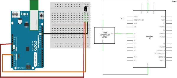
Sketch
Open the Arduino IDE software on your computer. Coding in the Arduino language will control your circuit. Open a new sketch File by clicking New.
Arduino Code
float temp;
int tempPin = 0;

void setup() {
   Serial.begin(9600);
}

void loop() {
   temp = analogRead(tempPin);
   // read analog volt from sensor and save to variable temp
   temp = temp * 0.48828125;
   // convert the analog volt to its temperature equivalent
   Serial.print("TEMPERATURE = ");
   Serial.print(temp); // display temperature value
   Serial.print("*C");
   Serial.println();
   delay(1000); // update sensor reading each one second
}
Code to Note
LM35 sensor has three terminals - Vs, Vout and GND. We will connect the sensor as follows −
- Connect the +Vs to +5v on your Arduino board.
- Connect Vout to Analog0 or A0 on Arduino board.
- Connect GND with GND on Arduino.
The Analog to Digital Converter (ADC) converts analog values into a digital approximation based on the formula ADC Value = sample * 1024 / reference voltage (+5v). So with a +5 volt reference, the digital approximation will be equal to input voltage * 205.
Result
You will see the temperature display on the serial port monitor which is updated every second.
Arduino - Water Detector / Sensor
Water sensor brick is designed for water detection, which can be widely used in sensing rainfall, water level, and even liquid leakage.
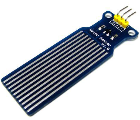
Connecting a water sensor to an Arduino is a great way to detect a leak, spill, flood, rain, etc. It can be used to detect the presence, the level, the volume and/or the absence of water. While this could be used to remind you to water your plants, there is a better Grove sensor for that. The sensor has an array of exposed traces, which read LOW when water is detected.
In this chapter, we will connect the water sensor to Digital Pin 8 on Arduino, and will enlist the very handy LED to help identify when the water sensor comes into contact with a source of water.
Components Required
You will need the following components −
- 1 × Breadboard
- 1 × Arduino Uno R3
- 1 × Water Sensor
- 1 × led
- 1 × 330 ohm resistor
Procedure
Follow the circuit diagram and hook up the components on the breadboard as shown in the image given below.
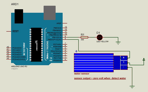
Sketch
Open the Arduino IDE software on your computer. Coding in the Arduino language will control your circuit. Open a new sketch File by clicking on New.
Arduino Code
#define Grove_Water_Sensor 8 // Attach Water sensor to Arduino Digital Pin 8
#define LED 9 // Attach an LED to Digital Pin 9 (or use onboard LED)

void setup() {
   pinMode(Grove_Water_Sensor, INPUT); // The Water Sensor is an Input
   pinMode(LED, OUTPUT); // The LED is an Output
}

void loop() {
   /* The water sensor will switch LOW when water is detected.
   Get the Arduino to illuminate the LED and activate the buzzer
   when water is detected, and switch both off when no water is present */
   if( digitalRead(Grove_Water_Sensor) == LOW) {
      digitalWrite(LED,HIGH);
   }else {
      digitalWrite(LED,LOW);
   }
}
Code to Note
Water sensor has three terminals - S, Vout(+), and GND (-). Connect the sensor as follows −
- Connect the +Vs to +5v on your Arduino board.
- Connect S to digital pin number 8 on Arduino board.
- Connect GND with GND on Arduino.
- Connect LED to digital pin number 9 in Arduino board.
When the sensor detects water, pin 8 on Arduino becomes LOW and then the LED on Arduino is turned ON.
Result
You will see the indication LED turn ON when the sensor detects water.
Arduino - PIR Sensor
PIR sensors allow you to sense motion. They are used to detect whether a human has moved in or out of the sensors range. They are commonly found in appliances and gadgets used at home or for businesses. They are often referred to as PIR, "Passive Infrared", "Pyroelectric", or "IR motion" sensors.
Following are the advantages of PIR Sensors −
- Small in size
- Wide lens range
- Easy to interface
- Inexpensive
- Low-power
- Easy to use
- Do not wear out
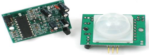
PIRs are made of pyroelectric sensors, a round metal can with a rectangular crystal in the center, which can detect levels of infrared radiation. Everything emits low-level radiation, and the hotter something is, the more radiation is emitted. The sensor in a motion detector is split in two halves. This is to detect motion (change) and not average IR levels. The two halves are connected so that they cancel out each other. If one-half sees more or less IR radiation than the other, the output will swing high or low.
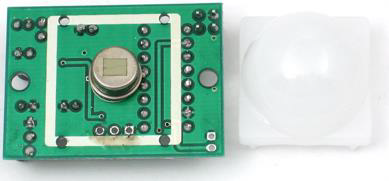
PIRs have adjustable settings and have a header installed in the 3-pin ground/out/power pads.
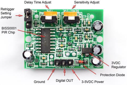
For many basic projects or products that need to detect when a person has left or entered the area, PIR sensors are great. Note that PIRs do not tell you the number of people around or their closeness to the sensor. The lens is often fixed to a certain sweep at a distance and they are sometimes set off by the pets in the house.
Components Required
You will need the following components −
- 1 × Breadboard
- 1 × Arduino Uno R3
- 1 × PIR Sensor (MQ3)
Procedure
Follow the circuit diagram and make the connections as shown in the image below.
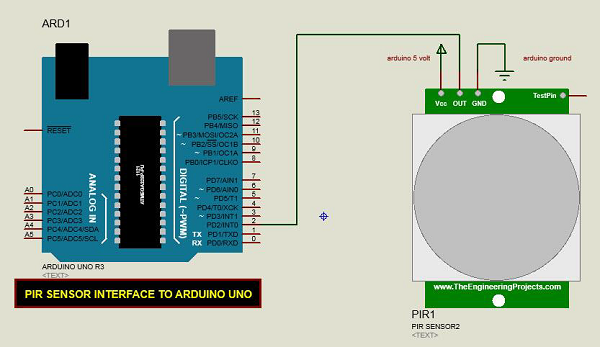
Sketch
Open the Arduino IDE software on your computer. Coding in the Arduino language will control your circuit. Open a new sketch File by clicking New.
Arduino Code
#define pirPin 2
int calibrationTime = 30;
long unsigned int lowIn;
long unsigned int pause = 5000;
boolean lockLow = true;
boolean takeLowTime;
int PIRValue = 0;

void setup() {
   Serial.begin(9600);
   pinMode(pirPin, INPUT);
}

void loop() {
   PIRSensor();
}

void PIRSensor() {
   if(digitalRead(pirPin) == HIGH) {
      if(lockLow) {
         PIRValue = 1;
         lockLow = false;
         Serial.println("Motion detected.");
         delay(50);
      }
      takeLowTime = true;
   }
   if(digitalRead(pirPin) == LOW) {
      if(takeLowTime){
         lowIn = millis();takeLowTime = false;
      }
      if(!lockLow && millis() - lowIn > pause) {
         PIRValue = 0;
         lockLow = true;
         Serial.println("Motion ended.");
         delay(50);
      }
   }
}
Code to Note
PIR sensor has three terminals - Vcc, OUT and GND. Connect the sensor as follows −
- Connect the +Vcc to +5v on Arduino board.
- Connect OUT to digital pin 2 on Arduino board.
- Connect GND with GND on Arduino.
You can adjust the sensor sensitivity and delay time via two variable resistors located at the bottom of the sensor board.

Once the sensor detects any motion, Arduino will send a message via the serial port to say that a motion is detected. The PIR sense motion will delay for certain time to check if there is a new motion. If there is no motion detected, Arduino will send a new message saying that the motion has ended.
Result
You will see a message on your serial port if a motion is detected and another message when the motion stops.
Arduino - Ultrasonic Sensor
The HC-SR04 ultrasonic sensor uses SONAR to determine the distance of an object just like the bats do. It offers excellent non-contact range detection with high accuracy and stable readings in an easy-to-use package from 2 cm to 400 cm or 1 to 13 feet.
The operation is not affected by sunlight or black material, although acoustically, soft materials like cloth can be difficult to detect. It comes complete with ultrasonic transmitter and receiver module.
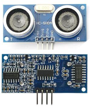
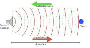
Technical Specifications
- Power Supply − +5V DC
- Quiescent Current − <2mA
- Working Current − 15mA
- Effectual Angle − <15
- Ranging Distance − 2cm 400 cm/1 13ft
- Resolution − 0.3 cm
- Measuring Angle − 30 degree
Components Required
You will need the following components −
- 1 × Breadboard
- 1 × Arduino Uno R3
- 1 × ULTRASONIC Sensor (HC-SR04)
Procedure
Follow the circuit diagram and make the connections as shown in the image given below.
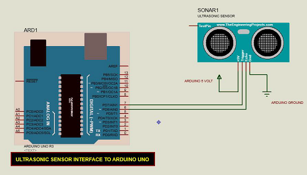
Sketch
Open the Arduino IDE software on your computer. Coding in the Arduino language will control your circuit. Open a new sketch File by clicking New.
Arduino Code
const int pingPin = 7; // Trigger Pin of Ultrasonic Sensor
const int echoPin = 6; // Echo Pin of Ultrasonic Sensor

void setup() {
   Serial.begin(9600); // Starting Serial Terminal
}

void loop() {
   long duration, inches, cm;
   pinMode(pingPin, OUTPUT);
   digitalWrite(pingPin, LOW);
   delayMicroseconds(2);
   digitalWrite(pingPin, HIGH);
   delayMicroseconds(10);
   digitalWrite(pingPin, LOW);
   pinMode(echoPin, INPUT);
   duration = pulseIn(echoPin, HIGH);
   inches = microsecondsToInches(duration);
   cm = microsecondsToCentimeters(duration);
   Serial.print(inches);
   Serial.print("in, ");
   Serial.print(cm);
   Serial.print("cm");
   Serial.println();
   delay(100);
}

long microsecondsToInches(long microseconds) {
   return microseconds / 74 / 2;
}

long microsecondsToCentimeters(long microseconds) {
   return microseconds / 29 / 2;
}
Code to Note
The Ultrasonic sensor has four terminals - +5V, Trigger, Echo, and GND connected as follows −
- Connect the +5V pin to +5v on your Arduino board.
- Connect Trigger to digital pin 7 on your Arduino board.
- Connect Echo to digital pin 6 on your Arduino board.
- Connect GND with GND on Arduino.
In our program, we have displayed the distance measured by the sensor in inches and cm via the serial port.
Result
You will see the distance measured by sensor in inches and cm on Arduino serial monitor.
Arduino - Connecting Switch
Pushbuttons or switches connect two open terminals in a circuit. This example turns on the LED on pin 2 when you press the pushbutton switch connected to pin 8.
Pull-down Resistor
Pull-down resistors are used in electronic logic circuits to ensure that inputs to Arduino settle at expected logic levels if external devices are disconnected or are at high-impedance. As nothing is connected to an input pin, it does not mean that it is a logical zero. Pull down resistors are connected between the ground and the appropriate pin on the device.
An example of a pull-down resistor in a digital circuit is shown in the following figure. A pushbutton switch is connected between the supply voltage and a microcontroller pin. In such a circuit, when the switch is closed, the micro-controller input is at a logical high value, but when the switch is open, the pull-down resistor pulls the input voltage down to the ground (logical zero value), preventing an undefined state at the input.
The pull-down resistor must have a larger resistance than the impedance of the logic circuit, or else it might pull the voltage down too much and the input voltage at the pin would remain at a constant logical low value, regardless of the switch position.
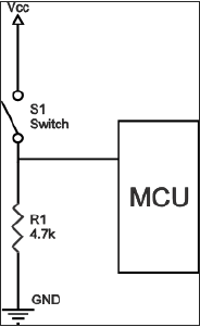
Components Required
You will need the following components −
- 1 × Arduino UNO board
- 1 × 330 ohm resistor
- 1 × 4.7K ohm resistor (pull down)
- 1 × LED
Procedure
Follow the circuit diagram and make the connections as shown in the image given below.

Sketch
Open the Arduino IDE software on your computer. Coding in the Arduino language will control your circuit. Open a new sketch File by clicking on New.
Arduino Code
// constants won't change. They're used here to
// set pin numbers:
const int buttonPin = 8; // the number of the pushbutton pin
const int ledPin = 2; // the number of the LED pin
// variables will change:
int buttonState = 0; // variable for reading the pushbutton status

void setup() {
   // initialize the LED pin as an output:
   pinMode(ledPin, OUTPUT);
   // initialize the pushbutton pin as an input:
   pinMode(buttonPin, INPUT);
}

void loop() {
   // read the state of the pushbutton value:
   buttonState = digitalRead(buttonPin);
   // check if the pushbutton is pressed.
   // if it is, the buttonState is HIGH:
   if (buttonState == HIGH) {
      // turn LED on:
      digitalWrite(ledPin, HIGH);
   } else {
      // turn LED off:
      digitalWrite(ledPin, LOW);
   }
}
Code to Note
When the switch is open, (pushbutton is not pressed), there is no connection between the two terminals of the pushbutton, so the pin is connected to the ground (through the pull-down resistor) and we read a LOW. When the switch is closed (pushbutton is pressed), it makes a connection between its two terminals, connecting the pin to 5 volts, so that we read a HIGH.
Result
LED is turned ON when the pushbutton is pressed and OFF when it is released.
Arduino - DC Motor
In this chapter, we will interface different types of motors with the Arduino board (UNO) and show you how to connect the motor and drive it from your board.
There are three different type of motors −
- DC motor
- Servo motor
- Stepper motor
A DC motor (Direct Current motor) is the most common type of motor. DC motors normally have just two leads, one positive and one negative. If you connect these two leads directly to a battery, the motor will rotate. If you switch the leads, the motor will rotate in the opposite direction.
Warning − Do not drive the motor directly from Arduino board pins. This may damage the board. Use a driver Circuit or an IC.
We will divide this chapter into three parts −
- Just make your motor spin
- Control motor speed
- Control the direction of the spin of DC motor
Components Required
You will need the following components −
- 1x Arduino UNO board
- 1x PN2222 Transistor
- 1x Small 6V DC Motor
- 1x 1N4001 diode
- 1x 270 Resistor
Procedure
Follow the circuit diagram and make the connections as shown in the image given below.
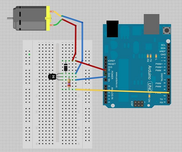
Precautions
Take the following precautions while making the connections.
First, make sure that the transistor is connected in the right way. The flat side of the transistor should face the Arduino board as shown in the arrangement.
Second, the striped end of the diode should be towards the +5V power line according to the arrangement shown in the image.
Spin ControlArduino Code
int motorPin = 3;

void setup() {

}

void loop() {
   digitalWrite(motorPin, HIGH);
}
Code to Note
The transistor acts like a switch, controlling the power to the motor. Arduino pin 3 is used to turn the transistor on and off and is given the name 'motorPin' in the sketch.
Result
Motor will spin in full speed when the Arduino pin number 3 goes high.
Motor Speed Control
Following is the schematic diagram of a DC motor, connected to the Arduino board.
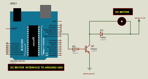
Arduino Code
int motorPin = 9;

void setup() {
   pinMode(motorPin, OUTPUT);
   Serial.begin(9600);
   while (! Serial);
   Serial.println("Speed 0 to 255");
}

void loop() {
   if (Serial.available()) {
      int speed = Serial.parseInt();
      if (speed >= 0 && speed <= 255) {
         analogWrite(motorPin, speed);
      }
   }
}
Code to Note
The transistor acts like a switch, controlling the power of the motor. Arduino pin 3 is used to turn the transistor on and off and is given the name 'motorPin' in the sketch.
When the program starts, it prompts you to give the values to control the speed of the motor. You need to enter a value between 0 and 255 in the Serial Monitor.
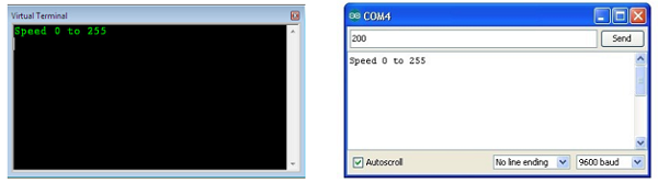
In the 'loop' function, the command 'Serial.parseInt' is used to read the number entered as text in the Serial Monitor and convert it into an 'int'. You can type any number here. The 'if' statement in the next line simply does an analog write with this number, if the number is between 0 and 255.
Result
The DC motor will spin with different speeds according to the value (0 to 250) received via the serial port.
Spin Direction Control
To control the direction of the spin of DC motor, without interchanging the leads, you can use a circuit called an H-Bridge. An H-bridge is an electronic circuit that can drive the motor in both directions. H-bridges are used in many different applications. One of the most common application is to control motors in robots. It is called an H-bridge because it uses four transistors connected in such a way that the schematic diagram looks like an "H."
We will be using the L298 H-Bridge IC here. The L298 can control the speed and direction of DC motors and stepper motors, and can control two motors simultaneously. Its current rating is 2A for each motor. At these currents, however, you will need to use heat sinks.
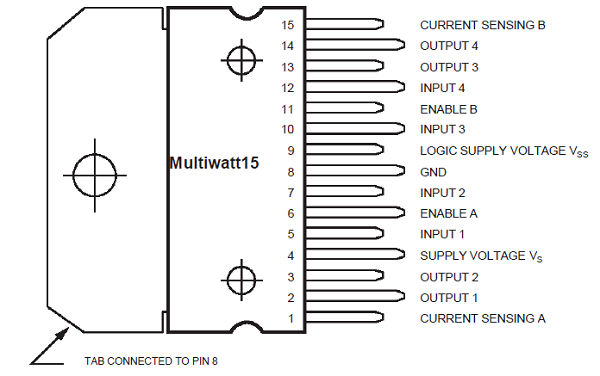
Components Required
You will need the following components −
- 1 × L298 bridge IC
- 1 × DC motor
- 1 × Arduino UNO
- 1 × breadboard
- 10 × jumper wires
Procedure
Following is the schematic diagram of the DC motor interface to Arduino Uno board.
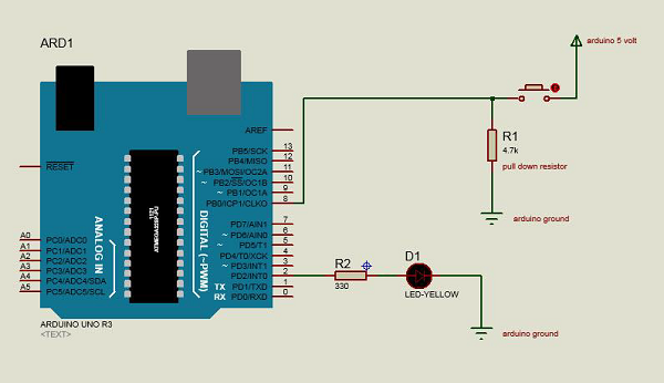
The above diagram shows how to connect the L298 IC to control two motors. There are three input pins for each motor, Input1 (IN1), Input2 (IN2), and Enable1 (EN1) for Motor1 and Input3, Input4, and Enable2 for Motor2.
Since we will be controlling only one motor in this example, we will connect the Arduino to IN1 (pin 5), IN2 (pin 7), and Enable1 (pin 6) of the L298 IC. Pins 5 and 7 are digital, i.e. ON or OFF inputs, while pin 6 needs a pulse-width modulated (PWM) signal to control the motor speed.
The following table shows which direction the motor will turn based on the digital values of IN1 and IN2.
| IN1 | IN2 | Motor Behavior |
|---|---|---|
| BRAKE | ||
| 1 | FORWARD | |
| 1 | BACKWARD | |
| 1 | 1 | BRAKE |
Pin IN1 of the IC L298 is connected to pin 8 of Arduino while IN2 is connected to pin 9. These two digital pins of Arduino control the direction of the motor. The EN A pin of IC is connected to the PWM pin 2 of Arduino. This will control the speed of the motor.
To set the values of Arduino pins 8 and 9, we have used the digitalWrite() function, and to set the value of pin 2, we have to use the analogWrite() function.
Connection Steps
- Connect 5V and the ground of the IC to 5V and the ground of Arduino, respectively.
- Connect the motor to pins 2 and 3 of the IC.
- Connect IN1 of the IC to pin 8 of Arduino.
- Connect IN2 of the IC to pin 9 of Arduino.
- Connect EN1 of IC to pin 2 of Arduino.
- Connect SENS A pin of IC to the ground.
- Connect Arduino using Arduino USB cable and upload the program to Arduino using Arduino IDE software.
- Provide power to Arduino board using power supply, battery, or USB cable.
Arduino Code
const int pwm = 2 ; //initializing pin 2 as pwm
const int in_1 = 8 ;
const int in_2 = 9 ;
//For providing logic to L298 IC to choose the direction of the DC motor

void setup() {
   pinMode(pwm,OUTPUT) ; //we have to set PWM pin as output
   pinMode(in_1,OUTPUT) ; //Logic pins are also set as output
   pinMode(in_2,OUTPUT) ;
}

void loop() {
   //For Clock wise motion , in_1 = High , in_2 = Low
   digitalWrite(in_1,HIGH) ;
   digitalWrite(in_2,LOW) ;
   analogWrite(pwm,255) ;
   /* setting pwm of the motor to 255 we can change the speed of rotation
   by changing pwm input but we are only using arduino so we are using highest
   value to driver the motor */
   //Clockwise for 3 secs
   delay(3000) ;
   //For brake
   digitalWrite(in_1,HIGH) ;
   digitalWrite(in_2,HIGH) ;
   delay(1000) ;
   //For Anti Clock-wise motion - IN_1 = LOW , IN_2 = HIGH
   digitalWrite(in_1,LOW) ;
   digitalWrite(in_2,HIGH) ;
   delay(3000) ;
   //For brake
   digitalWrite(in_1,HIGH) ;
   digitalWrite(in_2,HIGH) ;
   delay(1000) ;
}
Result
The motor will run first in the clockwise (CW) direction for 3 seconds and then counter-clockwise (CCW) for 3 seconds.
Arduino - Servo Motor
A Servo Motor is a small device that has an output shaft. This shaft can be positioned to specific angular positions by sending the servo a coded signal. As long as the coded signal exists on the input line, the servo will maintain the angular position of the shaft. If the coded signal changes, the angular position of the shaft changes. In practice, servos are used in radio-controlled airplanes to position control surfaces like the elevators and rudders. They are also used in radio-controlled cars, puppets, and of course, robots.
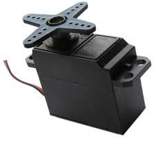
Servos are extremely useful in robotics. The motors are small, have built-in control circuitry, and are extremely powerful for their size. A standard servo such as the Futaba S-148 has 42 oz/inches of torque, which is strong for its size. It also draws power proportional to the mechanical load. A lightly loaded servo, therefore, does not consume much energy.
The guts of a servo motor is shown in the following picture. You can see the control circuitry, the motor, a set of gears, and the case. You can also see the 3 wires that connect to the outside world. One is for power (+5volts), ground, and the white wire is the control wire.
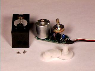
Working of a Servo Motor
The servo motor has some control circuits and a potentiometer (a variable resistor, aka pot) connected to the output shaft. In the picture above, the pot can be seen on the right side of the circuit board. This pot allows the control circuitry to monitor the current angle of the servo motor.
If the shaft is at the correct angle, then the motor shuts off. If the circuit finds that the angle is not correct, it will turn the motor until it is at a desired angle. The output shaft of the servo is capable of traveling somewhere around 180 degrees. Usually, it is somewhere in the 210-degree range, however, it varies depending on the manufacturer. A normal servo is used to control an angular motion of 0 to 180 degrees. It is mechanically not capable of turning any farther due to a mechanical stop built on to the main output gear.
The power applied to the motor is proportional to the distance it needs to travel. So, if the shaft needs to turn a large distance, the motor will run at full speed. If it needs to turn only a small amount, the motor will run at a slower speed. This is called proportional control.
How Do You Communicate the Angle at Which the Servo Should Turn?
The control wire is used to communicate the angle. The angle is determined by the duration of a pulse that is applied to the control wire. This is called Pulse Coded Modulation. The servo expects to see a pulse every 20 milliseconds (.02 seconds). The length of the pulse will determine how far the motor turns. A 1.5 millisecond pulse, for example, will make the motor turn to the 90-degree position (often called as the neutral position). If the pulse is shorter than 1.5 milliseconds, then the motor will turn the shaft closer to 0 degrees. If the pulse is longer than 1.5 milliseconds, the shaft turns closer to 180 degrees.
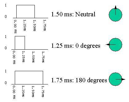
Components Required
You will need the following components −
- 1 × Arduino UNO board
- 1 × Servo Motor
- 1 × ULN2003 driving IC
- 1 × 10 K Resistor
Procedure
Follow the circuit diagram and make the connections as shown in the image given below.
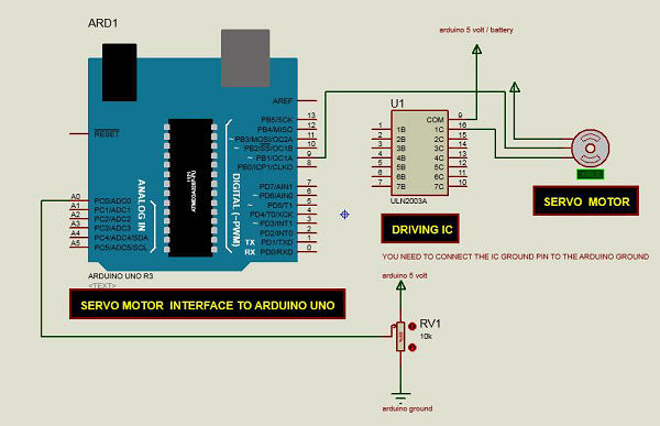
Sketch
Open the Arduino IDE software on your computer. Coding in the Arduino language will control your circuit. Open a new sketch File by clicking on New.
Arduino Code
/* Controlling a servo position using a potentiometer (variable resistor) */

#include <Servo.h>
   Servo myservo; // create servo object to control a servo
   int potpin = 0; // analog pin used to connect the potentiometer
   int val; // variable to read the value from the analog pin

void setup() {
   myservo.attach(9); // attaches the servo on pin 9 to the servo object
}

void loop() {
   val = analogRead(potpin);
   // reads the value of the potentiometer (value between 0 and 1023)
   val = map(val, 0, 1023, 0, 180);
   // scale it to use it with the servo (value between 0 and 180)
   myservo.write(val); // sets the servo position according to the scaled value
   delay(15);
}
Code to Note
Servo motors have three terminals - power, ground, and signal. The power wire is typically red, and should be connected to the 5V pin on the Arduino. The ground wire is typically black or brown and should be connected to one terminal of ULN2003 IC (10 -16). To protect your Arduino board from damage, you will need some driver IC to do that. Here we have used ULN2003 IC to drive the servo motor. The signal pin is typically yellow or orange and should be connected to Arduino pin number 9.
Connecting the Potentiometer
A voltage divider/potential divider are resistors in a series circuit that scale the output voltage to a particular ratio of the input voltage applied. Following is the circuit diagram −
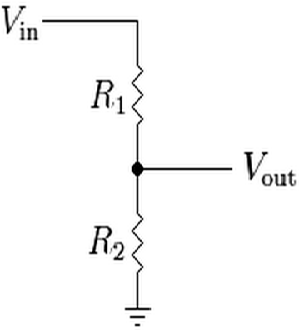
$$V_{out} = (V_{in} \times R_{2})/ (R_{1} + R_{2})$$
Vout is the output potential, which depends on the applied input voltage (Vin) and resistors (R1 and R2) in the series. It means that the current flowing through R1 will also flow through R2 without being divided. In the above equation, as the value of R2 changes, the Vout scales accordingly with respect to the input voltage, Vin.
Typically, a potentiometer is a potential divider, which can scale the output voltage of the circuit based on the value of the variable resistor, which is scaled using the knob. It has three pins: GND, Signal, and +5V as shown in the diagram below −
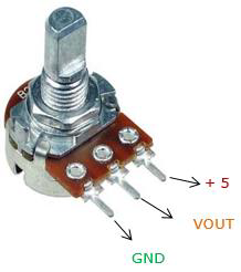
Result
By changing the pots NOP position, servo motor will change its angle.
Arduino - Stepper Motor
A Stepper Motor or a step motor is a brushless, synchronous motor, which divides a full rotation into a number of steps. Unlike a brushless DC motor, which rotates continuously when a fixed DC voltage is applied to it, a step motor rotates in discrete step angles.
The Stepper Motors therefore are manufactured with steps per revolution of 12, 24, 72, 144, 180, and 200, resulting in stepping angles of 30, 15, 5, 2.5, 2, and 1.8 degrees per step. The stepper motor can be controlled with or without feedback.
Imagine a motor on an RC airplane. The motor spins very fast in one direction or another. You can vary the speed with the amount of power given to the motor, but you cannot tell the propeller to stop at a specific position.
Now imagine a printer. There are lots of moving parts inside a printer, including motors. One such motor acts as the paper feed, spinning rollers that move the piece of paper as ink is being printed on it. This motor needs to be able to move the paper an exact distance to be able to print the next line of text or the next line of an image.
There is another motor attached to a threaded rod that moves the print head back and forth. Again, that threaded rod needs to be moved an exact amount to print one letter after another. This is where the stepper motors come in handy.
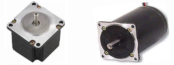
How a Stepper Motor Works?
A regular DC motor spins in only direction whereas a Stepper motor can spin in precise increments.
Stepper motors can turn an exact amount of degrees (or steps) as desired. This gives you total control over the motor, allowing you to move it to an exact location and hold that position. It does so by powering the coils inside the motor for very short periods of time. The disadvantage is that you have to power the motor all the time to keep it in the position that you desire.
All you need to know for now is that, to move a stepper motor, you tell it to move a certain number of steps in one direction or the other, and tell it the speed at which to step in that direction. There are numerous varieties of stepper motors. The methods described here can be used to infer how to use other motors and drivers which are not mentioned in this tutorial. However, it is always recommended that you consult the datasheets and guides of the motors and drivers specific to the models you have.
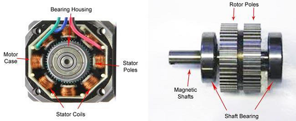
Components Required
You will need the following components −
- 1 × Arduino UNO board
- 1 × small bipolar stepper Motor as shown in the image given below
- 1 × LM298 driving IC
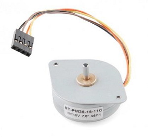
Procedure
Follow the circuit diagram and make the connections as shown in the image given below.
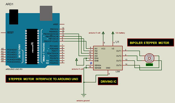
Sketch
Open the Arduino IDE software on your computer. Coding in the Arduino language will control your circuit. Open a new sketch File by clicking New.
Arduino Code
/* Stepper Motor Control */

#include <Stepper.h>
const int stepsPerRevolution = 90;
// change this to fit the number of steps per revolution
// for your motor
// initialize the stepper library on pins 8 through 11:
Stepper myStepper(stepsPerRevolution, 8, 9, 10, 11);

void setup() {
   // set the speed at 60 rpm:
   myStepper.setSpeed(5);
   // initialize the serial port:
   Serial.begin(9600);
}

void loop() {
   // step one revolution in one direction:
   Serial.println("clockwise");
   myStepper.step(stepsPerRevolution);
   delay(500);
   // step one revolution in the other direction:
   Serial.println("counterclockwise");
   myStepper.step(-stepsPerRevolution);
   delay(500);
}
Code to Note
This program drives a unipolar or bipolar stepper motor. The motor is attached to digital pins 8 - 11 of Arduino.
Result
The motor will take one revolution in one direction, then one revolution in the other direction.
Arduino - Tone Library
In this chapter, we will use the Arduino Tone Library. It is nothing but an Arduino Library, which produces square-wave of a specified frequency (and 50% duty cycle) on any Arduino pin. A duration can optionally be specified, otherwise the wave continues until the stop() function is called. The pin can be connected to a piezo buzzer or a speaker to play the tones.
Warning − Do not connect the pin directly to any audio input. The voltage is considerably higher than the standard line level voltages, and can damage sound card inputs, etc. You can use a voltage divider to bring the voltage down.
Components Required
You will need the following components −
- 1 × 8-ohm speaker
- 1 × 1k resistor
- 1 × Arduino UNO board
Procedure
Follow the circuit diagram and make the connections as shown in the image given below.
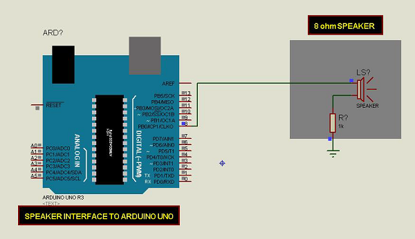
Sketch
Open the Arduino IDE software on your computer. Coding in the Arduino language will control your circuit. Open a new sketch File by clicking New.
To make the pitches.h file, either click the button just below the serial monitor icon and choose "New Tab", or use Ctrl+Shift+N.
Then paste the following code −
/*************************************************
* Public Constants
*************************************************/

#define NOTE_B0 31
#define NOTE_C1 33
#define NOTE_CS1 35
#define NOTE_D1 37
#define NOTE_DS1 39
#define NOTE_E1 41
#define NOTE_F1 44
#define NOTE_FS1 46
#define NOTE_G1 49
#define NOTE_GS1 52
#define NOTE_A1 55
#define NOTE_AS1 58
#define NOTE_B1 62
#define NOTE_C2 65
#define NOTE_CS2 69
#define NOTE_D2 73
#define NOTE_DS2 78
#define NOTE_E2 82
#define NOTE_F2 87
#define NOTE_FS2 93
#define NOTE_G2 98
#define NOTE_GS2 104
#define NOTE_A2 110
#define NOTE_AS2 117
#define NOTE_B2 123
#define NOTE_C3 131
#define NOTE_CS3 139
#define NOTE_D3 147
#define NOTE_DS3 156
#define NOTE_E3 165
#define NOTE_F3 175
#define NOTE_FS3 185
#define NOTE_G3 196
#define NOTE_GS3 208
#define NOTE_A3 220
#define NOTE_AS3 233
#define NOTE_B3 247
#define NOTE_C4 262
#define NOTE_CS4 277
#define NOTE_D4 294
#define NOTE_DS4 311
#define NOTE_E4 330
#define NOTE_F4 349
#define NOTE_FS4 370
#define NOTE_G4 392
#define NOTE_GS4 415
#define NOTE_A4 440
#define NOTE_AS4 466
#define NOTE_B4 494
#define NOTE_C5 523
#define NOTE_CS5 554
#define NOTE_D5 587
#define NOTE_DS5 622
#define NOTE_E5 659
#define NOTE_F5 698
#define NOTE_FS5 740
#define NOTE_G5 784
#define NOTE_GS5 831
#define NOTE_A5 880
#define NOTE_AS5 932
#define NOTE_B5 988
#define NOTE_C6 1047
#define NOTE_CS6 1109
#define NOTE_D6 1175
#define NOTE_DS6 1245
#define NOTE_E6 1319
#define NOTE_F6 1397
#define NOTE_FS6 1480
#define NOTE_G6 1568
#define NOTE_GS6 1661
#define NOTE_A6 1760
#define NOTE_AS6 1865
#define NOTE_B6 1976
#define NOTE_C7 2093
#define NOTE_CS7 2217
#define NOTE_D7 2349
#define NOTE_DS7 2489
#define NOTE_E7 2637
#define NOTE_F7 2794
#define NOTE_FS7 2960
#define NOTE_G7 3136
#define NOTE_GS7 3322
#define NOTE_A7 3520
#define NOTE_AS7 3729
#define NOTE_B7 3951
#define NOTE_C8 4186
#define NOTE_CS8 4435
#define NOTE_D8 4699
#define NOTE_DS8 4978
Save the above given code as pitches.h
Arduino Code
#include "pitches.h"
// notes in the melody:
int melody[] = {
NOTE_C4, NOTE_G3,NOTE_G3, NOTE_GS3, NOTE_G3,0, NOTE_B3, NOTE_C4};
// note durations: 4 = quarter note, 8 = eighth note, etc.:

int noteDurations[] = {
   4, 8, 8, 4,4,4,4,4
};

void setup() {
   // iterate over the notes of the melody:
   for (int thisNote = 0; thisNote < 8; thisNote++) {
      // to calculate the note duration, take one second
      // divided by the note type.
      //e.g. quarter note = 1000 / 4, eighth note = 1000/8, etc.
      int noteDuration = 1000/noteDurations[thisNote];
      tone(8, melody[thisNote],noteDuration);
      //pause for the note's duration plus 30 ms:
      delay(noteDuration +30);
   }
}

void loop() {
   // no need to repeat the melody.
}
Code to Note
The code uses an extra file, pitches.h. This file contains all the pitch values for typical notes. For example, NOTE_C4 is middle C. NOTE_FS4 is F sharp, and so forth. This note table was originally written by Brett Hagman, on whose work the tone() command was based. You may find it useful whenever you want to make musical notes.
Result
You will hear musical notes saved in the pitches.h. file.
Arduino - Wireless Communication
The wireless transmitter and receiver modules work at 315 Mhz. They can easily fit into a breadboard and work well with microcontrollers to create a very simple wireless data link. With one pair of transmitter and receiver, the modules will only work communicating data one-way, however, you would need two pairs (of different frequencies) to act as a transmitter/receiver pair.
Note − These modules are indiscriminate and receive a fair amount of noise. Both the transmitter and receiver work at common frequencies and do not have IDs.
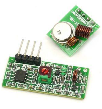
Receiver Module Specifications
- Product Model − MX-05V
- Operating voltage − DC5V
- Quiescent Current − 4mA
- Receiving frequency − 315Mhz
- Receiver sensitivity − -105DB
- Size − 30 * 14 * 7mm
Transmitter Module Specifications
- Product Model − MX-FS-03V
- Launch distance − 20-200 meters (different voltage, different results)
- Operating voltage − 3.5-12V
- Dimensions − 19 * 19mm
- Operating mode − AM
- Transfer rate − 4KB / S
- Transmitting power − 10mW
- Transmitting frequency − 315Mhz
- An external antenna − 25cm ordinary multi-core or single-core line
- Pinout from left → right − (DATA; VCC; GND)
Components Required
You will need the following components −
- 2 × Arduino UNO board
- 1 × Rf link transmitter
- 1 × Rf link receiver
Procedure
Follow the circuit diagram and make the connections as shown in the image given below.
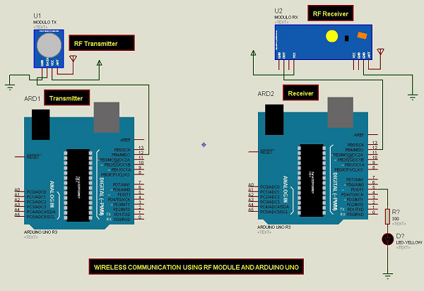
Sketch
Open the Arduino IDE software on your computer. Coding in the Arduino language will control your circuit. Open a new sketch File by clicking New.
Note − You must include the keypad library in your Arduino library file. Copy and paste the VirtualWire.lib file in the libraries folder as highlighted in the screenshot given below.
Arduino Code for Transmitter
//simple Tx on pin D12
#include <VirtualWire.h>
char *controller;

void setup() {
   pinMode(13,OUTPUT);
   vw_set_ptt_inverted(true);
   vw_set_tx_pin(12);
   vw_setup(4000);// speed of data transfer Kbps
}

void loop() {
   controller="1" ;
   vw_send((uint8_t *)controller, strlen(controller));
   vw_wait_tx(); // Wait until the whole message is gone
   digitalWrite(13,1);
   delay(2000);
   controller="0" ;
   vw_send((uint8_t *)controller, strlen(controller));
   vw_wait_tx(); // Wait until the whole message is gone
   digitalWrite(13,0);
   delay(2000);
}
Code to Note
This is a simple code. First, it will send character '1' and after two seconds it will send character '0' and so on.
Arduino Code for Receiver
//simple Rx on pin D12
#include <VirtualWire.h>

void setup() {
   vw_set_ptt_inverted(true); // Required for DR3100
   vw_set_rx_pin(12);
   vw_setup(4000); // Bits per sec
   pinMode(5, OUTPUT);
   vw_rx_start(); // Start the receiver PLL running
}

void loop() {
   uint8_t buf[VW_MAX_MESSAGE_LEN];
   uint8_t buflen = VW_MAX_MESSAGE_LEN;
   if (vw_get_message(buf, &buflen)) // Non-blocking {
      if(buf[0]=='1') {
         digitalWrite(5,1);
      }
      if(buf[0]=='0') {
         digitalWrite(5,0);
      }
   }
}
Code to Note
The LED connected to pin number 5 on the Arduino board is turned ON when character '1' is received and turned OFF when character '0' received.
Arduino - Network Communication
The CC3000 WiFi module from Texas Instruments is a small silver package, which finally brings easy-to-use, affordable WiFi functionality to your Arduino projects.
It uses SPI for communication (not UART!) so you can push data as fast as you want or as slow as you want. It has a proper interrupt system with IRQ pin so you can have asynchronous connections. It supports 802.11b/g, open/WEP/WPA/WPA2 security, TKIP & AES. A built-in TCP/IP stack with a "BSD socket" interface supports TCP and UDP in both the client and the server mode.
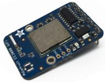
Components Required
You will need the following components −
- 1 × Arduino Uno
- 1 × Adafruit CC3000 breakout board
- 1 × 5V relay
- 1 × Rectifier diode
- 1 × LED
- 1 × 220 Ohm resistor
- 1 × Breadboard and some jumper wires
For this project, you just need the usual Arduino IDE, the Adafruits CC3000 library, and the CC3000 MDNS library. We are also going to use the aREST library to send commands to the relay via WiFi.
Procedure
Follow the circuit diagram and make the connections as shown in the image given below.
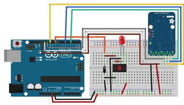
The hardware configuration for this project is very easy.
- Connect the IRQ pin of the CC3000 board to pin number 3 of the Arduino board.
- VBAT to pin 5, and CS to pin 10.
- Connect the SPI pins to Arduino board: MOSI, MISO, and CLK to pins 11, 12, and 13, respectively.
- Vin is connected to Arduino 5V, and GND to GND.
Let us now connect the relay.
After placing the relay on the breadboard, you can start identifying the two important parts on your relay: the coil part which commands the relay, and the switch part where we will attach the LED.
- First, connect pin number 8 of Arduino board to one pin of the coil.
- Connect the other pin to the ground of Arduino board.
You also have to place the rectifier diode (anode connected to the ground pin) over the pins of the coil to protect your circuit when the relay is switching.
Connect the +5V of Arduino board to the common pin of the relays switch.
Finally, connect one of the other pin of the switch (usually, the one which is not connected when the relay is off) to the LED in series with the 220 Ohm resistor, and connect the other side of the LED to the ground of Arduino board.
Testing Individual Components
You can test the relay with the following sketch −
const int relay_pin = 8; // Relay pin

void setup() {
   Serial.begin(9600);
   pinMode(relay_pin,OUTPUT);
}

void loop() {
   // Activate relay
   digitalWrite(relay_pin, HIGH);
   // Wait for 1 second
   delay(1000);
   // Deactivate relay
   digitalWrite(relay_pin, LOW);
   // Wait for 1 second
   delay(1000);
}
Code to Note
The code is self-explanatory. You can just upload it to the board and the relay will switch states every second, and the LED will switch ON and OFF accordingly.
Adding WiFi Connectivity
Let us now control the relay wirelessly using the CC3000 WiFi chip. The software for this project is based on the TCP protocol. However, for this project, Arduino board will be running a small web server, so we can listen for commands coming from the computer. We will first take care of Arduino sketch, and then we will see how to write the server-side code and create a nice interface.
First, the Arduino sketch. The goal here is to connect to your WiFi network, create a web server, check if there are incoming TCP connections, and then change the state of the relay accordingly.
Important Parts of the Code
#include <Adafruit_CC3000.h>
#include <SPI.h>
#include <CC3000_MDNS.h>
#include <Ethernet.h>
#include <aREST.h>
You need to define inside the code what is specific to your configuration, i.e. Wi-Fi name and password, and the port for TCP communications (we have used 80 here).
// WiFi network (change with your settings!)
   #define WLAN_SSID "yourNetwork" // cannot be longer than 32 characters!
   #define WLAN_PASS "yourPassword"
   #define WLAN_SECURITY WLAN_SEC_WPA2 // This can be WLAN_SEC_UNSEC, WLAN_SEC_WEP,
   // WLAN_SEC_WPA or WLAN_SEC_WPA2

// The port to listen for incoming TCP connections
   #define LISTEN_PORT 80
We can then create the CC3000 instance, server and aREST instance −
// Server instance
   Adafruit_CC3000_Server restServer(LISTEN_PORT); // DNS responder instance
   MDNSResponder mdns; // Create aREST instance
   aREST rest = aREST();
In the setup() part of the sketch, we can now connect the CC3000 chip to the network −
cc3000.connectToAP(WLAN_SSID, WLAN_PASS, WLAN_SECURITY);
How will the computer know where to send the data? One way would be to run the sketch once, then get the IP address of the CC3000 board, and modify the server code again. However, we can do better, and that is where the CC3000 MDNS library comes into play. We will assign a fixed name to our CC3000 board with this library, so we can write down this name directly into the server code.
This is done with the following piece of code −
if (!mdns.begin("arduino", cc3000)) {
   while(1);
}
We also need to listen for incoming connections.
restServer.begin();
Next, we will code the loop() function of the sketch that will be continuously executed. We first have to update the mDNS server.
mdns.update();
The server running on Arduino board will wait for the incoming connections and handle the requests.
Adafruit_CC3000_ClientRef client = restServer.available();
rest.handle(client);
It is now quite easy to test the projects via WiFi. Make sure you updated the sketch with your own WiFi name and password, and upload the sketch to your Arduino board. Open your Arduino IDE serial monitor, and look for the IP address of your board.
Let us assume for the rest here that it is something like 192.168.1.103.
Then, simply go to your favorite web browser, and type −
192.168.1.103/digital/8/1
You should see that your relay automatically turns ON.
Building the Relay Interface
We will now code the interface of the project. There will be two parts here: an HTML file containing the interface, and a client-side Javascript file to handle the clicks on the interface. The interface here is based on the aREST.js project, which was made to easily control WiFi devices from your computer.
Let us first see the HTML file, called interface.html. The first part consists importing all the required libraries for the interface −
<head>
   <meta charset = utf-8 />
   <title> Relay Control </title>
   <link rel = "stylesheet" type = "text/css"
      href = "https://maxcdn.bootstrapcdn.com/bootstrap/3.3.4/css/bootstrap.min.css">
   <link rel="stylesheet" type = "text/css" href = "style.css">
   <script type = "text/javascript"
      src = "https://code.jquery.com/jquery-2.1.4.min.js"></script>
   <script type = "text/javascript"
      src = "https://cdn.rawgit.com/Foliotek/AjaxQ/master/ajaxq.js"></script>
   <script type = "text/javascript"
      src = "https://cdn.rawgit.com/marcoschwartz/aREST.js/master/aREST.js"></script>
   <script type = "text/javascript"
      src = "script.js"></script>
</head>
Then, we define two buttons inside the interface, one to turn the relay on, and the other to turn it off again.
<div class = 'container'>
   <h1>Relay Control</h1>
   <div class = 'row'>
      <div class = "col-md-1">Relay</div>
      <div class = "col-md-2">
         <button id = 'on' class = 'btn btn-block btn-success'>On</button>
      </div>
      <div class = "col-md-2">
         <button id = 'off' class = 'btn btn-block btn-danger'>On</button>
      </div>
   </div>
</div>
Now, we also need a client-side Javascript file to handle the clicks on the buttons. We will also create a device that we will link to the mDNS name of our Arduino device. If you changed this in Arduino code, you will need to modify it here as well.
// Create device
var device = new Device("arduino.local");
// Button

$('#on').click(function() {
   device.digitalWrite(8, 1);
});

$('#off').click(function() {
   device.digitalWrite(8, 0);
});
The complete code for this project can be found on the GitHub repository. Go into the interface folder, and simply open the HTML file with your favorite browser. You should see something similar inside your browser −
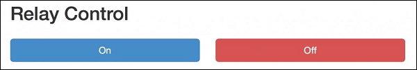
Try to click a button on the web interface; it should change the state of the relay nearly instantly.
If you managed to get it working, bravo! You just built a Wi-Fi-controlled light switch. Of course, you can control much more than lights with this project. Just make sure your relay supports the power required for the device you want to control, and you are good to go.
