- Arduino - Home
- Arduino - Overview
- Arduino - Board Description
- Arduino - Installation
- Arduino - Program Structure
- Arduino - Data Types
- Arduino - Variables & Constants
- Arduino - Operators
- Arduino - Control Statements
- Arduino - Loops
- Arduino - Functions
- Arduino - Strings
- Arduino - String Object
- Arduino - Time
- Arduino - Arrays
- Arduino Function Libraries
- Arduino - I/O Functions
- Arduino - Advanced I/O Function
- Arduino - Character Functions
- Arduino - Math Library
- Arduino - Trigonometric Functions
- Arduino Advanced
- Arduino - Due & Zero
- Arduino - Pulse Width Modulation
- Arduino - Random Numbers
- Arduino - Interrupts
- Arduino - Communication
- Arduino - Inter Integrated Circuit
- Arduino - Serial Peripheral Interface
- Arduino Projects
- Arduino - Blinking LED
- Arduino - Fading LED
- Arduino - Reading Analog Voltage
- Arduino - LED Bar Graph
- Arduino - Keyboard Logout
- Arduino - Keyboard Message
- Arduino - Mouse Button Control
- Arduino - Keyboard Serial
- Arduino Sensors
- Arduino - Humidity Sensor
- Arduino - Temperature Sensor
- Arduino - Water Detector / Sensor
- Arduino - PIR Sensor
- Arduino - Ultrasonic Sensor
- Arduino - Connecting Switch
- Motor Control
- Arduino - DC Motor
- Arduino - Servo Motor
- Arduino - Stepper Motor
- Arduino And Sound
- Arduino - Tone Library
- Arduino - Wireless Communication
- Arduino - Network Communication
Arduino - Serial Peripheral Interface
A Serial Peripheral Interface (SPI) bus is a system for serial communication, which uses up to four conductors, commonly three. One conductor is used for data receiving, one for data sending, one for synchronization and one alternatively for selecting a device to communicate with. It is a full duplex connection, which means that the data is sent and received simultaneously. The maximum baud rate is higher than that in the I2C communication system.
Board SPI Pins
SPI uses the following four wires −
SCK − This is the serial clock driven by the master.
MOSI − This is the master output / slave input driven by the master.
MISO − This is the master input / slave output driven by the master.
SS − This is the slave-selection wire.
The following functions are used. You have to include the SPI.h.
SPI.begin() − Initializes the SPI bus by setting SCK, MOSI, and SS to outputs, pulling SCK and MOSI low, and SS high.
SPI.setClockDivider(divider) − To set the SPI clock divider relative to the system clock. On AVR based boards, the dividers available are 2, 4, 8, 16, 32, 64 or 128. The default setting is SPI_CLOCK_DIV4, which sets the SPI clock to one-quarter of the frequency of the system clock (5 Mhz for the boards at 20 MHz).
Divider − It could be (SPI_CLOCK_DIV2, SPI_CLOCK_DIV4, SPI_CLOCK_DIV8, SPI_CLOCK_DIV16, SPI_CLOCK_DIV32, SPI_CLOCK_DIV64, SPI_CLOCK_DIV128).
SPI.transfer(val) − SPI transfer is based on a simultaneous send and receive: the received data is returned in receivedVal.
SPI.beginTransaction(SPISettings(speedMaximum, dataOrder, dataMode)) − speedMaximum is the clock, dataOrder(MSBFIRST or LSBFIRST), dataMode(SPI_MODE0, SPI_MODE1, SPI_MODE2, or SPI_MODE3).
We have four modes of operation in SPI as follows −
Mode 0 (the default) − Clock is normally low (CPOL = 0), and the data is sampled on the transition from low to high (leading edge) (CPHA = 0).
Mode 1 − Clock is normally low (CPOL = 0), and the data is sampled on the transition from high to low (trailing edge) (CPHA = 1).
Mode 2 − Clock is normally high (CPOL = 1), and the data is sampled on the transition from high to low (leading edge) (CPHA = 0).
Mode 3 − Clock is normally high (CPOL = 1), and the data is sampled on the transition from low to high (trailing edge) (CPHA = 1).
SPI.attachInterrupt(handler) − Function to be called when a slave device receives data from the master.
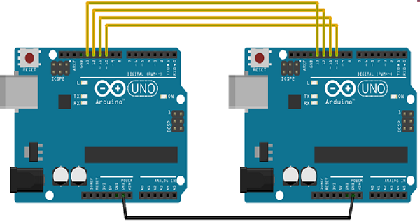
Now, we will connect two Arduino UNO boards together; one as a master and the other as a slave.
- (SS) : pin 10
- (MOSI) : pin 11
- (MISO) : pin 12
- (SCK) : pin 13
The ground is common. Following is the diagrammatic representation of the connection between both the boards −
Let us see examples of SPI as Master and SPI as Slave.
SPI as MASTER
Example
#include <SPI.h>

void setup (void) {
   Serial.begin(115200); //set baud rate to 115200 for usart
   digitalWrite(SS, HIGH); // disable Slave Select
   SPI.begin ();
   SPI.setClockDivider(SPI_CLOCK_DIV8);//divide the clock by 8
}

void loop (void) {
   char c;
   digitalWrite(SS, LOW); // enable Slave Select
   // send test string
   for (const char * p = "Hello, world!\r" ; c = *p; p++) {
      SPI.transfer (c);
      Serial.print(c);
   }
   digitalWrite(SS, HIGH); // disable Slave Select
   delay(2000);
}
SPI as SLAVE
Example
#include <SPI.h>
char buff [50];
volatile byte indx;
volatile boolean process;

void setup (void) {
   Serial.begin (115200);
   pinMode(MISO, OUTPUT); // have to send on master in so it set as output
   SPCR |= _BV(SPE); // turn on SPI in slave mode
   indx = 0; // buffer empty
   process = false;
   SPI.attachInterrupt(); // turn on interrupt
}
ISR (SPI_STC_vect) // SPI interrupt routine {
   byte c = SPDR; // read byte from SPI Data Register
   if (indx < sizeof buff) {
      buff [indx++] = c; // save data in the next index in the array buff
      if (c == '\r') //check for the end of the word
      process = true;
   }
}

void loop (void) {
   if (process) {
      process = false; //reset the process
      Serial.println (buff); //print the array on serial monitor
      indx= 0; //reset button to zero
   }
}
