- Arduino - Home
- Arduino - Overview
- Arduino - Board Description
- Arduino - Installation
- Arduino - Program Structure
- Arduino - Data Types
- Arduino - Variables & Constants
- Arduino - Operators
- Arduino - Control Statements
- Arduino - Loops
- Arduino - Functions
- Arduino - Strings
- Arduino - String Object
- Arduino - Time
- Arduino - Arrays
- Arduino Function Libraries
- Arduino - I/O Functions
- Arduino - Advanced I/O Function
- Arduino - Character Functions
- Arduino - Math Library
- Arduino - Trigonometric Functions
- Arduino Advanced
- Arduino - Due & Zero
- Arduino - Pulse Width Modulation
- Arduino - Random Numbers
- Arduino - Interrupts
- Arduino - Communication
- Arduino - Inter Integrated Circuit
- Arduino - Serial Peripheral Interface
- Arduino Projects
- Arduino - Blinking LED
- Arduino - Fading LED
- Arduino - Reading Analog Voltage
- Arduino - LED Bar Graph
- Arduino - Keyboard Logout
- Arduino - Keyboard Message
- Arduino - Mouse Button Control
- Arduino - Keyboard Serial
- Arduino Sensors
- Arduino - Humidity Sensor
- Arduino - Temperature Sensor
- Arduino - Water Detector / Sensor
- Arduino - PIR Sensor
- Arduino - Ultrasonic Sensor
- Arduino - Connecting Switch
- Motor Control
- Arduino - DC Motor
- Arduino - Servo Motor
- Arduino - Stepper Motor
- Arduino And Sound
- Arduino - Tone Library
- Arduino - Wireless Communication
- Arduino - Network Communication
Arduino - Wireless Communication
The wireless transmitter and receiver modules work at 315 Mhz. They can easily fit into a breadboard and work well with microcontrollers to create a very simple wireless data link. With one pair of transmitter and receiver, the modules will only work communicating data one-way, however, you would need two pairs (of different frequencies) to act as a transmitter/receiver pair.
Note − These modules are indiscriminate and receive a fair amount of noise. Both the transmitter and receiver work at common frequencies and do not have IDs.
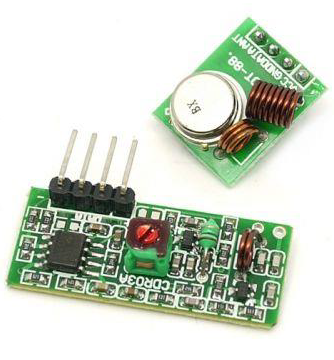
Receiver Module Specifications
- Product Model − MX-05V
- Operating voltage − DC5V
- Quiescent Current − 4mA
- Receiving frequency − 315Mhz
- Receiver sensitivity − -105DB
- Size − 30 * 14 * 7mm
Transmitter Module Specifications
- Product Model − MX-FS-03V
- Launch distance − 20-200 meters (different voltage, different results)
- Operating voltage − 3.5-12V
- Dimensions − 19 * 19mm
- Operating mode − AM
- Transfer rate − 4KB / S
- Transmitting power − 10mW
- Transmitting frequency − 315Mhz
- An external antenna − 25cm ordinary multi-core or single-core line
- Pinout from left → right − (DATA; VCC; GND)
Components Required
You will need the following components −
- 2 × Arduino UNO board
- 1 × Rf link transmitter
- 1 × Rf link receiver
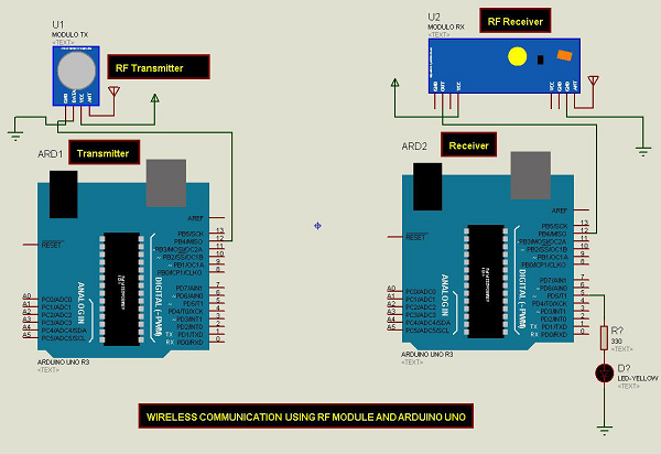
Procedure
Follow the circuit diagram and make the connections as shown in the image given below.
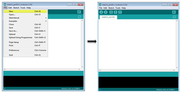
Sketch
Open the Arduino IDE software on your computer. Coding in the Arduino language will control your circuit. Open a new sketch File by clicking New.
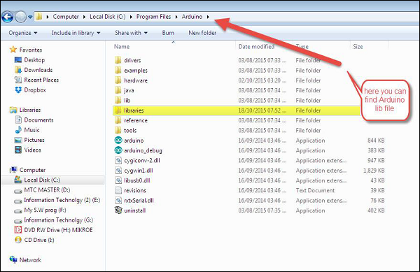
Note − You must include the keypad library in your Arduino library file. Copy and paste the VirtualWire.lib file in the libraries folder as highlighted in the screenshot given below.
Arduino Code for Transmitter
//simple Tx on pin D12
#include <VirtualWire.h>
char *controller;

void setup() {
   pinMode(13,OUTPUT);
   vw_set_ptt_inverted(true);
   vw_set_tx_pin(12);
   vw_setup(4000);// speed of data transfer Kbps
}

void loop() {
   controller="1" ;
   vw_send((uint8_t *)controller, strlen(controller));
   vw_wait_tx(); // Wait until the whole message is gone
   digitalWrite(13,1);
   delay(2000);
   controller="0" ;
   vw_send((uint8_t *)controller, strlen(controller));
   vw_wait_tx(); // Wait until the whole message is gone
   digitalWrite(13,0);
   delay(2000);
}
Code to Note
This is a simple code. First, it will send character '1' and after two seconds it will send character '0' and so on.
Arduino Code for Receiver
//simple Rx on pin D12
#include <VirtualWire.h>

void setup() {
   vw_set_ptt_inverted(true); // Required for DR3100
   vw_set_rx_pin(12);
   vw_setup(4000); // Bits per sec
   pinMode(5, OUTPUT);
   vw_rx_start(); // Start the receiver PLL running
}

void loop() {
   uint8_t buf[VW_MAX_MESSAGE_LEN];
   uint8_t buflen = VW_MAX_MESSAGE_LEN;
   if (vw_get_message(buf, &buflen)) // Non-blocking {
      if(buf[0]=='1') {
         digitalWrite(5,1);
      }
      if(buf[0]=='0') {
         digitalWrite(5,0);
      }
   }
}
Code to Note
The LED connected to pin number 5 on the Arduino board is turned ON when character '1' is received and turned OFF when character '0' received.
