- Arduino - Home
- Arduino - Overview
- Arduino - Board Description
- Arduino - Installation
- Arduino - Program Structure
- Arduino - Data Types
- Arduino - Variables & Constants
- Arduino - Operators
- Arduino - Control Statements
- Arduino - Loops
- Arduino - Functions
- Arduino - Strings
- Arduino - String Object
- Arduino - Time
- Arduino - Arrays
- Arduino Function Libraries
- Arduino - I/O Functions
- Arduino - Advanced I/O Function
- Arduino - Character Functions
- Arduino - Math Library
- Arduino - Trigonometric Functions
- Arduino Advanced
- Arduino - Due & Zero
- Arduino - Pulse Width Modulation
- Arduino - Random Numbers
- Arduino - Interrupts
- Arduino - Communication
- Arduino - Inter Integrated Circuit
- Arduino - Serial Peripheral Interface
- Arduino Projects
- Arduino - Blinking LED
- Arduino - Fading LED
- Arduino - Reading Analog Voltage
- Arduino - LED Bar Graph
- Arduino - Keyboard Logout
- Arduino - Keyboard Message
- Arduino - Mouse Button Control
- Arduino - Keyboard Serial
- Arduino Sensors
- Arduino - Humidity Sensor
- Arduino - Temperature Sensor
- Arduino - Water Detector / Sensor
- Arduino - PIR Sensor
- Arduino - Ultrasonic Sensor
- Arduino - Connecting Switch
- Motor Control
- Arduino - DC Motor
- Arduino - Servo Motor
- Arduino - Stepper Motor
- Arduino And Sound
- Arduino - Tone Library
- Arduino - Wireless Communication
- Arduino - Network Communication
Arduino - Servo Motor
A Servo Motor is a small device that has an output shaft. This shaft can be positioned to specific angular positions by sending the servo a coded signal. As long as the coded signal exists on the input line, the servo will maintain the angular position of the shaft. If the coded signal changes, the angular position of the shaft changes. In practice, servos are used in radio-controlled airplanes to position control surfaces like the elevators and rudders. They are also used in radio-controlled cars, puppets, and of course, robots.
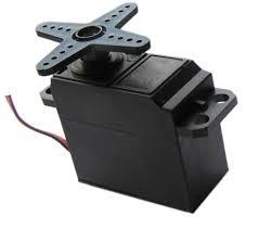
Servos are extremely useful in robotics. The motors are small, have built-in control circuitry, and are extremely powerful for their size. A standard servo such as the Futaba S-148 has 42 oz/inches of torque, which is strong for its size. It also draws power proportional to the mechanical load. A lightly loaded servo, therefore, does not consume much energy.
The guts of a servo motor is shown in the following picture. You can see the control circuitry, the motor, a set of gears, and the case. You can also see the 3 wires that connect to the outside world. One is for power (+5volts), ground, and the white wire is the control wire.
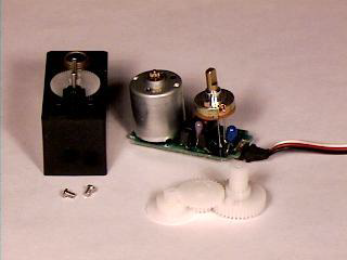
Working of a Servo Motor
The servo motor has some control circuits and a potentiometer (a variable resistor, aka pot) connected to the output shaft. In the picture above, the pot can be seen on the right side of the circuit board. This pot allows the control circuitry to monitor the current angle of the servo motor.
If the shaft is at the correct angle, then the motor shuts off. If the circuit finds that the angle is not correct, it will turn the motor until it is at a desired angle. The output shaft of the servo is capable of traveling somewhere around 180 degrees. Usually, it is somewhere in the 210-degree range, however, it varies depending on the manufacturer. A normal servo is used to control an angular motion of 0 to 180 degrees. It is mechanically not capable of turning any farther due to a mechanical stop built on to the main output gear.
The power applied to the motor is proportional to the distance it needs to travel. So, if the shaft needs to turn a large distance, the motor will run at full speed. If it needs to turn only a small amount, the motor will run at a slower speed. This is called proportional control.
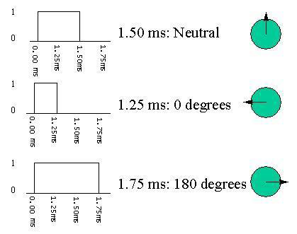
How Do You Communicate the Angle at Which the Servo Should Turn?
The control wire is used to communicate the angle. The angle is determined by the duration of a pulse that is applied to the control wire. This is called Pulse Coded Modulation. The servo expects to see a pulse every 20 milliseconds (.02 seconds). The length of the pulse will determine how far the motor turns. A 1.5 millisecond pulse, for example, will make the motor turn to the 90-degree position (often called as the neutral position). If the pulse is shorter than 1.5 milliseconds, then the motor will turn the shaft closer to 0 degrees. If the pulse is longer than 1.5 milliseconds, the shaft turns closer to 180 degrees.
Components Required
You will need the following components −
- 1 × Arduino UNO board
- 1 × Servo Motor
- 1 × ULN2003 driving IC
- 1 × 10 K Resistor
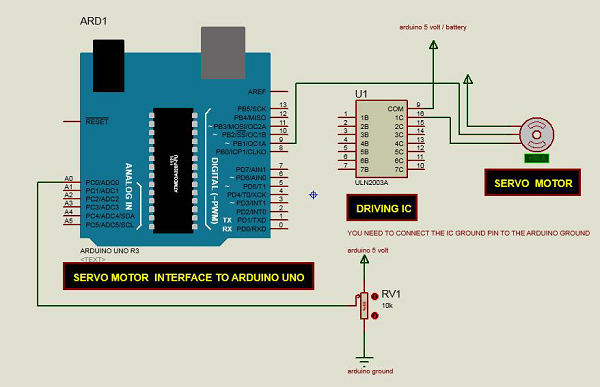
Procedure
Follow the circuit diagram and make the connections as shown in the image given below.
Sketch
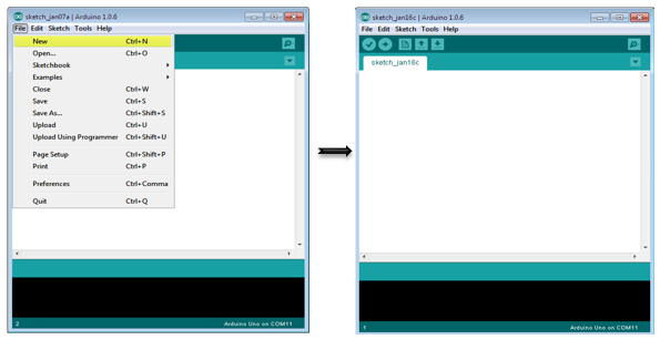
Open the Arduino IDE software on your computer. Coding in the Arduino language will control your circuit. Open a new sketch File by clicking on New.
Arduino Code
/* Controlling a servo position using a potentiometer (variable resistor) */

#include <Servo.h>
   Servo myservo; // create servo object to control a servo
   int potpin = 0; // analog pin used to connect the potentiometer
   int val; // variable to read the value from the analog pin

void setup() {
   myservo.attach(9); // attaches the servo on pin 9 to the servo object
}

void loop() {
   val = analogRead(potpin);
   // reads the value of the potentiometer (value between 0 and 1023)
   val = map(val, 0, 1023, 0, 180);
   // scale it to use it with the servo (value between 0 and 180)
   myservo.write(val); // sets the servo position according to the scaled value
   delay(15);
}
Code to Note
Servo motors have three terminals - power, ground, and signal. The power wire is typically red, and should be connected to the 5V pin on the Arduino. The ground wire is typically black or brown and should be connected to one terminal of ULN2003 IC (10 -16). To protect your Arduino board from damage, you will need some driver IC to do that. Here we have used ULN2003 IC to drive the servo motor. The signal pin is typically yellow or orange and should be connected to Arduino pin number 9.
Connecting the Potentiometer
A voltage divider/potential divider are resistors in a series circuit that scale the output voltage to a particular ratio of the input voltage applied. Following is the circuit diagram −
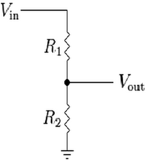
$$V_{out} = (V_{in} \times R_{2})/ (R_{1} + R_{2})$$
Vout is the output potential, which depends on the applied input voltage (Vin) and resistors (R1 and R2) in the series. It means that the current flowing through R1 will also flow through R2 without being divided. In the above equation, as the value of R2 changes, the Vout scales accordingly with respect to the input voltage, Vin.
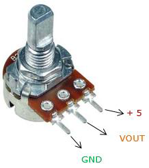
Typically, a potentiometer is a potential divider, which can scale the output voltage of the circuit based on the value of the variable resistor, which is scaled using the knob. It has three pins: GND, Signal, and +5V as shown in the diagram below −
Result
By changing the pots NOP position, servo motor will change its angle.
