- Arduino - Home
- Arduino - Overview
- Arduino - Board Description
- Arduino - Installation
- Arduino - Program Structure
- Arduino - Data Types
- Arduino - Variables & Constants
- Arduino - Operators
- Arduino - Control Statements
- Arduino - Loops
- Arduino - Functions
- Arduino - Strings
- Arduino - String Object
- Arduino - Time
- Arduino - Arrays
- Arduino Function Libraries
- Arduino - I/O Functions
- Arduino - Advanced I/O Function
- Arduino - Character Functions
- Arduino - Math Library
- Arduino - Trigonometric Functions
- Arduino Advanced
- Arduino - Due & Zero
- Arduino - Pulse Width Modulation
- Arduino - Random Numbers
- Arduino - Interrupts
- Arduino - Communication
- Arduino - Inter Integrated Circuit
- Arduino - Serial Peripheral Interface
- Arduino Projects
- Arduino - Blinking LED
- Arduino - Fading LED
- Arduino - Reading Analog Voltage
- Arduino - LED Bar Graph
- Arduino - Keyboard Logout
- Arduino - Keyboard Message
- Arduino - Mouse Button Control
- Arduino - Keyboard Serial
- Arduino Sensors
- Arduino - Humidity Sensor
- Arduino - Temperature Sensor
- Arduino - Water Detector / Sensor
- Arduino - PIR Sensor
- Arduino - Ultrasonic Sensor
- Arduino - Connecting Switch
- Motor Control
- Arduino - DC Motor
- Arduino - Servo Motor
- Arduino - Stepper Motor
- Arduino And Sound
- Arduino - Tone Library
- Arduino - Wireless Communication
- Arduino - Network Communication
Arduino - Network Communication
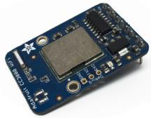
The CC3000 WiFi module from Texas Instruments is a small silver package, which finally brings easy-to-use, affordable WiFi functionality to your Arduino projects.
It uses SPI for communication (not UART!) so you can push data as fast as you want or as slow as you want. It has a proper interrupt system with IRQ pin so you can have asynchronous connections. It supports 802.11b/g, open/WEP/WPA/WPA2 security, TKIP & AES. A built-in TCP/IP stack with a "BSD socket" interface supports TCP and UDP in both the client and the server mode.
Components Required
You will need the following components −
- 1 × Arduino Uno
- 1 × Adafruit CC3000 breakout board
- 1 × 5V relay
- 1 × Rectifier diode
- 1 × LED
- 1 × 220 Ohm resistor
- 1 × Breadboard and some jumper wires
For this project, you just need the usual Arduino IDE, the Adafruits CC3000 library, and the CC3000 MDNS library. We are also going to use the aREST library to send commands to the relay via WiFi.
Procedure
Follow the circuit diagram and make the connections as shown in the image given below.
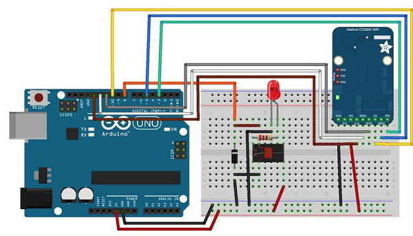
The hardware configuration for this project is very easy.
- Connect the IRQ pin of the CC3000 board to pin number 3 of the Arduino board.
- VBAT to pin 5, and CS to pin 10.
- Connect the SPI pins to Arduino board: MOSI, MISO, and CLK to pins 11, 12, and 13, respectively.
- Vin is connected to Arduino 5V, and GND to GND.
Let us now connect the relay.
After placing the relay on the breadboard, you can start identifying the two important parts on your relay: the coil part which commands the relay, and the switch part where we will attach the LED.
- First, connect pin number 8 of Arduino board to one pin of the coil.
- Connect the other pin to the ground of Arduino board.
You also have to place the rectifier diode (anode connected to the ground pin) over the pins of the coil to protect your circuit when the relay is switching.
Connect the +5V of Arduino board to the common pin of the relays switch.
Finally, connect one of the other pin of the switch (usually, the one which is not connected when the relay is off) to the LED in series with the 220 Ohm resistor, and connect the other side of the LED to the ground of Arduino board.
Testing Individual Components
You can test the relay with the following sketch −
const int relay_pin = 8; // Relay pin

void setup() {
   Serial.begin(9600);
   pinMode(relay_pin,OUTPUT);
}

void loop() {
   // Activate relay
   digitalWrite(relay_pin, HIGH);
   // Wait for 1 second
   delay(1000);
   // Deactivate relay
   digitalWrite(relay_pin, LOW);
   // Wait for 1 second
   delay(1000);
}
Code to Note
The code is self-explanatory. You can just upload it to the board and the relay will switch states every second, and the LED will switch ON and OFF accordingly.
Adding WiFi Connectivity
Let us now control the relay wirelessly using the CC3000 WiFi chip. The software for this project is based on the TCP protocol. However, for this project, Arduino board will be running a small web server, so we can listen for commands coming from the computer. We will first take care of Arduino sketch, and then we will see how to write the server-side code and create a nice interface.
First, the Arduino sketch. The goal here is to connect to your WiFi network, create a web server, check if there are incoming TCP connections, and then change the state of the relay accordingly.
Important Parts of the Code
#include <Adafruit_CC3000.h>
#include <SPI.h>
#include <CC3000_MDNS.h>
#include <Ethernet.h>
#include <aREST.h>
You need to define inside the code what is specific to your configuration, i.e. Wi-Fi name and password, and the port for TCP communications (we have used 80 here).
// WiFi network (change with your settings!)
   #define WLAN_SSID "yourNetwork" // cannot be longer than 32 characters!
   #define WLAN_PASS "yourPassword"
   #define WLAN_SECURITY WLAN_SEC_WPA2 // This can be WLAN_SEC_UNSEC, WLAN_SEC_WEP,
   // WLAN_SEC_WPA or WLAN_SEC_WPA2

// The port to listen for incoming TCP connections
   #define LISTEN_PORT 80
We can then create the CC3000 instance, server and aREST instance −
// Server instance
   Adafruit_CC3000_Server restServer(LISTEN_PORT); // DNS responder instance
   MDNSResponder mdns; // Create aREST instance
   aREST rest = aREST();
In the setup() part of the sketch, we can now connect the CC3000 chip to the network −
cc3000.connectToAP(WLAN_SSID, WLAN_PASS, WLAN_SECURITY);
How will the computer know where to send the data? One way would be to run the sketch once, then get the IP address of the CC3000 board, and modify the server code again. However, we can do better, and that is where the CC3000 MDNS library comes into play. We will assign a fixed name to our CC3000 board with this library, so we can write down this name directly into the server code.
This is done with the following piece of code −
if (!mdns.begin("arduino", cc3000)) {
   while(1);
}
We also need to listen for incoming connections.
restServer.begin();
Next, we will code the loop() function of the sketch that will be continuously executed. We first have to update the mDNS server.
mdns.update();
The server running on Arduino board will wait for the incoming connections and handle the requests.
Adafruit_CC3000_ClientRef client = restServer.available();
rest.handle(client);
It is now quite easy to test the projects via WiFi. Make sure you updated the sketch with your own WiFi name and password, and upload the sketch to your Arduino board. Open your Arduino IDE serial monitor, and look for the IP address of your board.
Let us assume for the rest here that it is something like 192.168.1.103.
Then, simply go to your favorite web browser, and type −
192.168.1.103/digital/8/1
You should see that your relay automatically turns ON.
Building the Relay Interface
We will now code the interface of the project. There will be two parts here: an HTML file containing the interface, and a client-side Javascript file to handle the clicks on the interface. The interface here is based on the aREST.js project, which was made to easily control WiFi devices from your computer.
Let us first see the HTML file, called interface.html. The first part consists importing all the required libraries for the interface −
<head>
   <meta charset = utf-8 />
   <title> Relay Control </title>
   <link rel = "stylesheet" type = "text/css"
      href = "https://maxcdn.bootstrapcdn.com/bootstrap/3.3.4/css/bootstrap.min.css">
   <link rel="stylesheet" type = "text/css" href = "style.css">
   <script type = "text/javascript"
      src = "https://code.jquery.com/jquery-2.1.4.min.js"></script>
   <script type = "text/javascript"
      src = "https://cdn.rawgit.com/Foliotek/AjaxQ/master/ajaxq.js"></script>
   <script type = "text/javascript"
      src = "https://cdn.rawgit.com/marcoschwartz/aREST.js/master/aREST.js"></script>
   <script type = "text/javascript"
      src = "script.js"></script>
</head>
Then, we define two buttons inside the interface, one to turn the relay on, and the other to turn it off again.
<div class = 'container'>
   <h1>Relay Control</h1>
   <div class = 'row'>
      <div class = "col-md-1">Relay</div>
      <div class = "col-md-2">
         <button id = 'on' class = 'btn btn-block btn-success'>On</button>
      </div>
      <div class = "col-md-2">
         <button id = 'off' class = 'btn btn-block btn-danger'>On</button>
      </div>
   </div>
</div>
Now, we also need a client-side Javascript file to handle the clicks on the buttons. We will also create a device that we will link to the mDNS name of our Arduino device. If you changed this in Arduino code, you will need to modify it here as well.
// Create device
var device = new Device("arduino.local");
// Button

$('#on').click(function() {
   device.digitalWrite(8, 1);
});

$('#off').click(function() {
   device.digitalWrite(8, 0);
});
The complete code for this project can be found on the GitHub repository. Go into the interface folder, and simply open the HTML file with your favorite browser. You should see something similar inside your browser −
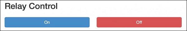
Try to click a button on the web interface; it should change the state of the relay nearly instantly.
If you managed to get it working, bravo! You just built a Wi-Fi-controlled light switch. Of course, you can control much more than lights with this project. Just make sure your relay supports the power required for the device you want to control, and you are good to go.
