
Article Categories
- All Categories
-
 Data Structure
-
 Networking
-
 RDBMS
RDBMS
-
 Operating System
-
 Java
Java
-
 MS Excel
-
 iOS
iOS
-
 HTML
HTML
-
 CSS
CSS
-
 Android
-
 Python
-
 C Programming
-
 C++
C++
-
 C#
C#
-
 MongoDB
-
 MySQL
MySQL
-
 Javascript
-
 PHP
PHP
-
 Economics & Finance
Overview of the working of 8259
The interrupt requests are accepted by 8259 from many interrupting devices IR0 to IR7 pins. After that, it identifies the highest priority interrupt request from those inputs that are already active. To configure the 8259 for fixed priority mode of operation, among them IR0 has the highest and IR7 has the lowest priority. If the inputs IR2, IR4, and IR6 are active, thenIR2 has the highest priority interrupt request among the active requests than the other. The details of the interrupt requests those are active are stored in the Interrupt Request Register (IRR).
By loading the Interrupt Mask Register (IMR), it is possible to mask the interrupt request. If the interrupt requests IR2 and IR3 are masked, then IR4 will get the highest priority interrupt request among the active requests that are not masked. It is possible that the processor is already servicing IR5 interrupt request. All the information about the interrupt requests that are presently services is kept in In-Service Register in short abbreviation (ISR).
Apriority resolver unit exists in 8259 which receives inputs requests from IRR, ISR, and IMR and identifies the highest priority interrupt request. Since the priority of IR4 is much greater than IR5 which is currently being serviced, the INT (Interrupt Request) of the output is activated. At the same time, bit no 4 of ISR is set to 1 by the8259. The output of INT of 8259 is connected to INTR input of 8085 as shown in the figure below. The INT output of 8259 should not get connected to any other interrupt pin of 8085.
Hence the priority resolver decides to activate the INT output only when the following conditions are satisfied otherwise not.
Activation to IR input is done
When the masking of the IR input is not done
When the processor is currently not servicing an IR request with a higher priority.
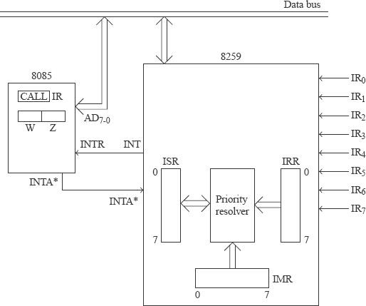
Fig − 8259 interfaced along with 8085 processor
8085 executes the instruction during which the INTR input was activated. Then the 8085sends out INTA* output thrice in succession assuming that the 8085 interrupt system is enabled, and higher priority interrupts of 8085 are not active. In response to the activation of INTA*, the 8259 sends to the 8085 using the D7-0 pins a 3-byte CALL instruction. The first time the INTA* is activated, the 8259 sends the code for CALL (5CDH) to the 8085 on D7-0 pins. It is received in the IR register of 8085. The second time the INTA*is activated the 8259 sends LS byte of interrupt vector (IV) address to the 8085 on D7-0 pins. It is received in the Z register of 8085. The third time the INTA* is activated the 8259 sends MS byte of IV address to the 8085 on D7-0 pins. It is received in the W register of 8085. The IV address supplied by the 8259 to the 8085 depends on the IR input of 8259 that is being serviced. This results in a branch to the appropriate ISS. After finishing the ISS the control returns to the main program.
The important thing to note is that the processor is not required to identify the source of the interrupt on the INTR pin. The 8259 has the mechanism to identify the source of an interrupt from among IR0 to IR7. It sends to the 8085the CALL instruction with appropriate ISS address accordingly. Thus the problem of polling is eliminated and so the interrupt response time is reduced. Second, the 8259 could be configured to operate in“rotating priority mode”. Then the disadvantage of fixed priority is also taken care of.
By using a single 8259 in the system, eight interrupting devices can interrupt on the input of INTR of 8085. When a number of devices need toper form the interrupt-driven data transfer scheme, multiple 8259s are used.
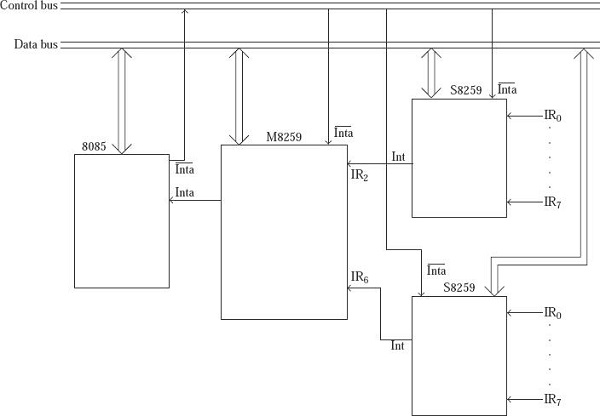
Fig − Multiple 8259s are used.

2K+ Views
