
Article Categories
- All Categories
-
 Data Structure
-
 Networking
-
 RDBMS
RDBMS
-
 Operating System
-
 Java
Java
-
 MS Excel
-
 iOS
iOS
-
 HTML
HTML
-
 CSS
CSS
-
 Android
-
 Python
-
 C Programming
-
 C++
C++
-
 C#
C#
-
 MongoDB
-
 MySQL
MySQL
-
 Javascript
-
 PHP
PHP
-
 Economics & Finance
8259 PIC Microprocessor
The 8259 is known as the Programmable Interrupt Controller (PIC) microprocessor. In 8085 and 8086 there are five hardware interrupts and two hardware interrupts respectively. Bu adding 8259, we can increase the interrupt handling capability. This chip combines the multi-interrupt input source to single interrupt output. This provides 8-interrupts from IR0 to IR7. Let us see some features of this microprocessor.
This chip is designed for 8085 and 8086.
It can be programmed either in edge triggered, or in level triggered mode
We can mask individual bits of Interrupt Request Register.
By cascading 8259 chips, we can increase interrupts up to 64 interrupt lines
Clock cycle is not needed.
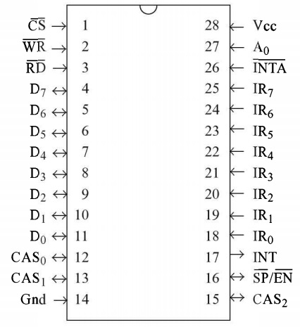
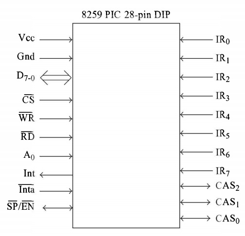
The pin level diagram and functional pin diagram is like below -
The block diagram is like below -
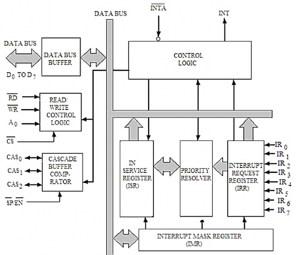
|
Block |
Description |
|---|---|
|
Data Bus Buffer |
This block is used to communicate between 8259 and 8085/8086 by acting as buffer. It takes the control word from 8085/8086 and send it to the 8259. It transfers the opcode of the selected interrupts and address of ISR to the other connected microprocessor. It can send maximum 8-bit at a time. |
|
R/W Control Logic |
This block works when the value of pin CS is 0. This block is used to flow the data depending upon the inputs of RD and WR. These are active low pins for read and write. |
|
Control Logic |
It controls the functionality of each block. It has pin called INTR. This is connected to other microprocessors for taking the interrupt request. The INT pin is used to give the output. If 8259 is enabled, and also the interrupt flags of other microprocessors are high then this causes the value of the output INT pin high, and in this way this chip can responds requests made by other microprocessors. |
|
Interrupt Request Register |
It stores all interrupt level that are requesting for interrupt service. |
|
Interrupt Service Register |
It stores interrupt level that are currently being execute. |
|
Interrupt Mask Register |
It stores interrupt level that will be masked, by storing the masking bits of interrupt level. |
|
Priority Resolver |
It checks all three registers, and set the priority of the interrupts. Interrupt with the highest priority is set in the ISR register. It also reset the interrupt level which is already been serviced in the IRR. |
|
Cascade Buffer |
To increase number of interrupt pin, we can cascade more number of pins, by using cascade buffer. When we are going to increase the interrupt capability, CSA lines are used to control multiple interrupts. |

30K+ Views
