
Article Categories
- All Categories
-
 Data Structure
-
 Networking
-
 RDBMS
RDBMS
-
 Operating System
-
 Java
Java
-
 MS Excel
-
 iOS
iOS
-
 HTML
HTML
-
 CSS
CSS
-
 Android
-
 Python
-
 C Programming
-
 C++
C++
-
 C#
C#
-
 MongoDB
-
 MySQL
MySQL
-
 Javascript
-
 PHP
PHP
-
 Economics & Finance
Magnetic Circuit – Series and Parallel Magnetic Circuit
Magnetic Circuit
A magnetic circuit is defined as a closed path followed by the magnetic flux.
A magnetic circuit consists of a core of materials having high permeability like iron, soft steel etc. It is because these materials offer very small opposition to the flow of magnetic flux.
Consider a coil of N turns wound on an iron core (see the figure). When an electric current I is passes through the coil, magnetic flux (ψ) is set up in the core. This magnetic flux follows a closed path ABCDA and hence ABCDA is the magnetic circuit.
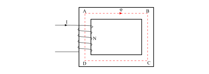
In a magnetic circuit, the amount of magnetic flux in the core depends upon the current (I) and the number of turns (N). The product NI is known as the Magnetomotive Force (MMF).
$$\mathrm{MMF = NI= Ampere − Turns}$$
The opposition offered by the magnetic circuit to the flow of magnetic flux is known as reluctance (S) of the magnetic circuit. The reluctance of the magnetic circuit depends upon the length of magnetic circuit, cross-sectional area of the circuit and nature of the material that makes up the magnetic circuit.
Types of Magnetic Circuit
There are two types of magnetic circuits −
- Series Magnetic Circuit
- Parallel Magnetic Circuit
Series Magnetic Circuit
When the same magnetic flux ψ flows through each part of the magnetic circuit, then the circuit is called as series magnetic circuit.
Consider a composite series magnetic circuit (a series magnetic circuit that has parts of different dimensions and materials is called a composite series magnetic circuit) consisting of two different magnetic materials of different relative permeability. Each part of this series magnetic circuit will offer reluctance to the magnetic flux ψ. Since the different parts of the magnetic circuit are in series, the total reluctance is equal to the sum of reluctances of individual parts.
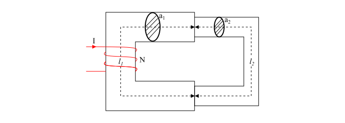
Referring the figure of series magnetic circuit, we have,
$$\mathrm{Total\: Reluctance,\mathit{S_{T}=\frac{l_{1}}{\mu_{0}\mu_{r1}a_{1}}+\frac{l_{2}}{\mu_{0}\mu_{r2}a_{2}}}}$$
$$\mathrm{Total \:MMF =Magnetic\: flux \times\: Total\: Reluctance}$$
$$\mathrm{\Longrightarrow Total \:MMF =\mathit{ψ(\frac{l_{1}}{\mu_{0}\mu_{r1}a_{1}}+\frac{l_{2}}{\mu_{0}\mu_{r2}a_{2}}})}$$
$$\mathrm{\Longrightarrow Total\: MMF =\mathit{(\frac{B_{1}}{\mu_{0}\mu_{r2}})\times l_{1}+(\frac{B_{2}}{\mu_{0}\mu_{r2}})\times l_{2}}}$$
$$\mathrm{\Longrightarrow Total\: MMF = \mathit{H_{1}\times l_{1}+H_{2}\times l_{2}}}$$
Therefore, total MMF required to set up the magnetic flux in a series magnetic circuit is the sum of MMF required by individual parts of the circuit.
Parallel Magnetic Circuit
A magnetic circuit which has more one path for the magnetic flux is called as parallel magnetic circuit.
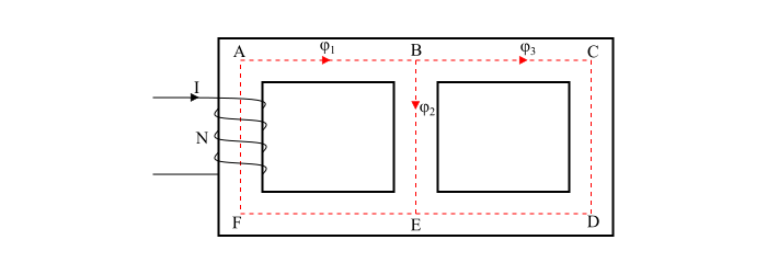
Consider a coil of N turns wound on limb AF carries an electric current of I amperes. The magnetic flux $\varphi_{1}$ set up by the coil divides at B into two paths viz. −
- The magnetic $\varphi_{2}$ passes along the path BE.
- The magnetic flux $\varphi_{3}$ passes along the path BCDE.
Therefore, the total flux is,
$$\mathrm{\mathit{\varphi_{1}=\varphi_{2}+\varphi_{3}}}$$
The path BE and BCDE are in parallel and hence form a parallel magnetic circuit. In a parallel magnetic circuit, the MMF required for the whole parallel magnetic circuit is equal to MMF required for any one of the parallel paths.
Let
$$\mathrm{\mathit{S_{1}} = Reluctance\: of\: magnetic\: path \:ABEF}$$
$$\mathrm{\mathit{S_{2}} = Reluctance\: of\: magnetic\: path \:BE}$$
$$\mathrm{\mathit{S_{3}} = Reluctance \:of\: magnetic\: path\: BCDE}$$
Therefore,
$$\mathrm{Total \:MMF = MMF \:for\: path\: ABEF + MMF \:for\: path\: BE\: or \:BCDE}$$
$$\mathrm{\Longrightarrow Total\: MMF = \mathit{\varphi_{1}S_{1}+ ψ_{2}S_{2}+ \varphi_{3}S_{3}}}$$

23K+ Views
