 Data Structure
 Networking
 RDBMS
RDBMS Operating System
 Java
Java MS Excel
 iOS
iOS HTML
HTML CSS
CSS Android
 Python
 C Programming
 C++
C++ C#
C# MongoDB
 MySQL
MySQL Javascript
 PHP
PHP
- Selected Reading
- UPSC IAS Exams Notes
- Developer's Best Practices
- Questions and Answers
- Effective Resume Writing
- HR Interview Questions
- Computer Glossary
- Who is Who
Parallel Circuit: Definition and Examples
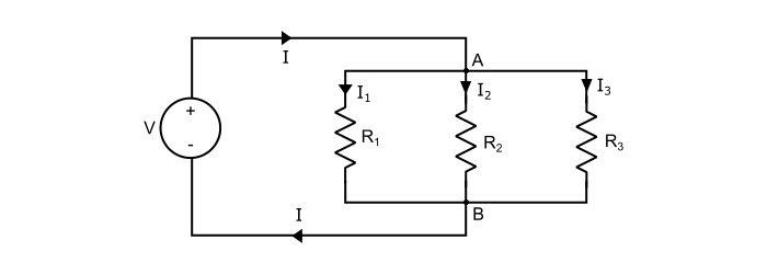
When the resistances are connected with each other such that one end of each resistance is joined to a common point and the other end of each resistance is joined to another common point so that the number paths for the current flow is equal to the number of resistances, it is called a parallel circuit.
Explanation
Consider three resistors R1, R2 and R3 connected across a source of voltage V as shown in the circuit diagram. The total current (I) divides in three parts – I1 flowing through R1, I2 flowing through R2 and I3 flowing through R3. As, it can be seen that the voltage across each resistance is the same.

By Ohm’s law, current through each resistor is given by,
$$\mathrm{\mathit{I}_{1}=\frac{\mathit{V}}{\mathit{R}_{1}};\:\:\:\mathit{I}_{2}=\frac{\mathit{V}}{\mathit{R}_{2}}\:\:\:and\:\:\:I_{3}=\frac{\mathit{V}}{\mathit{R}_{3}};}$$
Referring the circuit, the total current is,
$$\mathrm{\mathit{I}=\mathit{I}_{1}\:+\:\mathit{I}_{2}\:+\:\mathit{I}_{3}}$$
$$\mathrm{\Rightarrow\:\mathit{I}=\frac{\mathit{V}}{\mathit{R}_{1}}+\frac{\mathit{V}}{\mathit{R}_{2}}+\frac{\mathit{V}}{\mathit{R}_{3}}=\mathit{V}(\frac{1}{\mathit{R}_{1}}+\frac{1}{\mathit{R}_{2}}+\frac{1}{\mathit{R}_{3}})}$$
$$\mathrm{\Rightarrow\:\frac{1}{\mathit{V}}=(\frac{1}{\mathit{R}_{1}}+\frac{1}{\mathit{R}_{2}}+\frac{1}{\mathit{R}_{3}})}$$
$$\mathrm{?\:\frac{1}{\mathit{V}}=\frac{1}{\mathit{R}_{p}}}$$
$$\mathrm{?\:\frac{1}{\mathit{R}_{p}}=(\frac{1}{\mathit{R}_{1}}+\frac{1}{\mathit{R}_{2}}+\frac{1}{\mathit{R}_{3}})}$$
Hence, when a number of resistance are connected in parallel, the reciprocal of total resistance is equal to the sum of the reciprocals of the individual resistances.
Also,
$$\mathrm{?\:\frac{1}{\mathit{R}}=\mathit{G}(Conductance)}$$
$$\mathrm{?\:\mathit{G}_{p}=\mathit{G}_{1}+\mathit{G}_{2}+\mathit{G}_{3}}$$
Thus, total conductance GP of resistors which are connected in parallel is equal to the sum of their individual conductances.
The total power dissipated in the circuit is equal to sum of powers dissipated in the individual resistances. Thus,
$$\mathrm{\frac{1}{\mathit{R}_{p}}=(\frac{1}{\mathit{R}_{1}}+\frac{1}{\mathit{R}_{2}}+\frac{1}{\mathit{R}_{3}})}$$
$$\mathrm{\Rightarrow\frac{\mathit{V}^{2}}{\mathit{R}_{p}}=\frac{\mathit{V}^{2}}{\mathit{R}_{1}}+\frac{\mathit{V}^{2}}{\mathit{R}_{2}}+\frac{\mathit{V}^{2}}{\mathit{R}_{3}}}$$
$$\mathrm{\Rightarrow\:\mathit{P}_{p}=\mathit{P}_{1}+\mathit{P}_{2}+\mathit{P}_{3}}$$
Important Points about Parallel Circuit
The voltage across each branch is same.
As the number of parallel branches is increased, the total resistance of the circuit is decreased.
The total resistance of the circuit is less than the smallest of the resistances.
The total conductance is equal to sum of their individual conductances.
The total power dissipated in the circuit is equal to sum of powers dissipated in the individual resistances.
Numerical Example
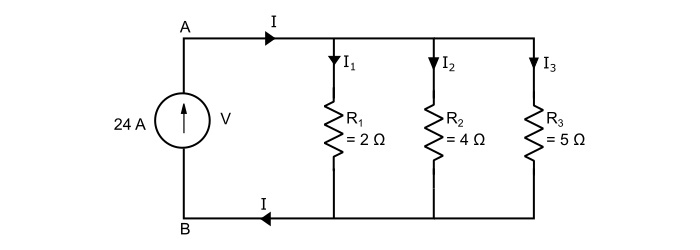
What is the potential difference between points A and B, also find the three branch currents in the circuit shown below?

Solution
The equivalent resistance (RP) of the three parallel connected resistors is
$$\mathrm{\frac{1}{\mathit{R}_{p}}=\frac{1}{2}+\frac{1}{4}+\frac{1}{5}=\frac{19}{20}}$$
$$\mathrm{\Rightarrow\:{\mathit{R}_{p}}=1.053 \:Ω}$$
Therefore, the voltage V across the terminals A and B is
$$\mathrm{\mathit{V}=I\mathit{R}_{p}=24×1.053=25.27\:Volts}$$
Now, the branch currents are
$$\mathrm{Current\:\mathit{I}_{1}=\frac{\mathit{V}}{\mathit{R}_{1}}=\frac{25.27}{2}=12.64\:A}$$
$$\mathrm{Current\:\mathit{I}_{2}=\frac{\mathit{V}}{\mathit{R}_{2}}=\frac{25.27}{4}=6.32\:A}$$
$$\mathrm{Current\:\mathit{I}_{3}=\frac{\mathit{V}}{\mathit{R}_{3}}=\frac{25.27}{5}=5.05\:A}$$

