
Article Categories
- All Categories
-
 Data Structure
-
 Networking
-
 RDBMS
RDBMS
-
 Operating System
-
 Java
Java
-
 MS Excel
-
 iOS
iOS
-
 HTML
HTML
-
 CSS
CSS
-
 Android
-
 Python
-
 C Programming
-
 C++
C++
-
 C#
C#
-
 MongoDB
-
 MySQL
MySQL
-
 Javascript
-
 PHP
PHP
-
 Economics & Finance
Series RLC Circuit: Analysis and Example Problems
Consider the circuit consisting of R, L and C connected in series across a supply voltage of V (RMS) volts. The resulting current I (RMS) is flowing in the circuit. Since the R, L and C are connected in series, thus current is same through all the three elements. For the convenience of the analysis, the current can be taken as reference phasor. Therefore,
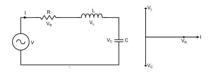
$$\mathrm{Voltage\:acorss\:\mathit{R},\mathit{V}_{R}=\mathit{IR}}$$
$$\mathrm{Voltage\:acorss\:\mathit{L},\mathit{V}_{L}=\mathit{IX}_{L}}$$
$$\mathrm{Voltage\:acorss\:\mathit{C},\mathit{V}_{C}=\mathit{IX}_{c}}$$
Where,
- XL = jωL = Inductive Reactince,
- Xc = 1/jωC = Capacitive reactance.
- VR is in phase with I.
- VL is leading the current I by 90°.
- VC is lagging the I by 90°.
The total voltage is the phasor sum of VR, VL and VC, i.e.,
$$\mathrm{\mathit{V} = \mathit{V}_{R}+\mathit{V}_{L}+\mathit{V}_{C}}$$
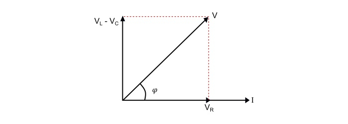
$$\mathrm{Magnitude\:of\:voltage,|\mathit{V}|=\sqrt{\mathit{V}_{R}^{2}+(\mathit{V}_{L}-\mathit{V}_{C})^{2}}}$$
$$\mathrm{\Rightarrow\:|\mathit{V}|=\sqrt{(\mathit{IR})^{2}+(\mathit{IX}_{L}-\mathit{IX}_{C})^{2}}=I\sqrt{(R)^{2}+(X_{L}-X_{C})^{2}}}$$
$$\mathrm{Phase\:angle\:of\:voltage,\Phi=\tan^{-1}(\frac{V_{L}-V_{C}}{V_{R}})=\tan^{-1}(\frac{\mathit{X}_{L}-\mathit{X}_{C}}{R})}$$
Therefore,
$$\mathrm{Circuit\:current,\mathit{I}=\frac{|V|\angle\Phi}{\sqrt{(R)^{2}+(\mathit{X}_{L}-\mathit{X}_{C})^{2}}}}$$
Where, $(\sqrt{(\mathit{R})^{2}+(\mathit{X}_{L}-\mathit{X}_{C})^{2}})$ is the opposition offered to the current flow and is known as Impedance of the circuit. It is denoted by Z, thus,
$$\mathrm{\mathit{Z}=\mathit{R}+\mathit{X}_{L}+\mathit{X}_{C}=\mathit{R}+\mathit{j}(\omega L-\frac{1}{\omega C})}$$
$$\mathrm{Magnitude\:of\:impedance,|\mathit{Z}|=\sqrt{(\mathit{R})^{2}+(\mathit{X}_{L}-\mathit{X}_{C})^{2}}}$$
$$\mathrm{Impedance\:angle,\theta=\tan^{-1}(\frac{\mathit{X}_{L}-\mathit{X}_{C}}{\mathit{R}})}$$
Circuit Power Factor
The power of an AC circuit is defined as the ration of active power to the total power. i.e.
$$\mathrm{Power\:Factor,Cos\Phi=\frac{Active\:power}{Total\:Power}}$$
$$\mathrm{\Rightarrow\:Cos\Phi=\frac{\mathit{I}^{2}\mathit{R}}{\mathit{I}^{2}\mathit{Z}}=\frac{R}{Z}=\frac{\mathit{R}}{\sqrt{(\mathit{R})^{2}+(\mathit{X}_{L}-\mathit{X}_{C})^{2}}}}$$
Power Consumed
The power is consumed in the circuit only by the resistor, the inductor and capacitor does consume any power. Therefore,
$$\mathrm{\mathit{P}=VICos\Phi=(\mathit{IZ})×\mathit{I}×\frac{\mathit{R}}{Z}=\mathit{I}^{2}\mathit{R}}$$
Three cases of series RLC circuit
Case 1 – When XL > XC, i.e. (XL - XC) is positive, thus, the phase angle φ is positive, so the circuit behaves as an inductive circuit and has lagging power factor.
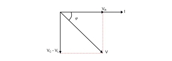
Case 2 – When XL C, i.e. (XL - XC) is negative, thus, the phase angle φ is negative, so the circuit behaves as an inductive circuit and has lagging power factor.
Case 3 – When XL = XC, i.e. (XL - XC) is zero, thus, the phase angle φ is zero, so the circuit acts as a purely resistive circuit and has unity power factor.

Now, if the applied voltage is given by,
$$\mathrm{\nu=\mathit{V}_{m}sin(\omega t)}$$
Then, the equation of the circuit current will be,
$$\mathrm{i=\mathit{I}_{m}sin(\omega t\:±\:\Phi)}$$
The value of φ will be positive or negative depending upon which reactance (XL or XC) predominates.
Series Resonance
The resonance occurs in a series RLC circuit, when the reactive component of the impedance becomes zero, i.e.
$$\mathrm{(\mathit{X}_{L}-\mathit{X}_{C})=0}$$
$$\mathrm{\Rightarrow(\omega L-\frac{1}{\omega \mathit{C}})=0}$$
$$\mathrm{\Rightarrow\:\omega L=\frac{1}{\omega \mathit{C}}}$$
Therefore, the resonant frequency is
$$\mathrm{\omega_{0}=\frac{1}{\sqrt{\mathit{LC}}}}$$
Effects of series resonance
- XL = XC,thus ω0 = $1/ \sqrt{LC}$
- ZR = R = Minimum
- Circuit current at resonance, Ir = V/R =Maximum.
- Circuit power factor is unity. Hence, circuit is purely resistive.
- The voltage across inductor and capacitor being equal, i.e. VL= VC.
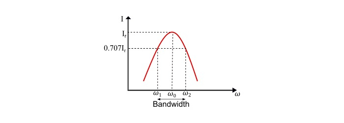
Resonance Curve
The curve between current and frequency is known as resonance curve.
Since,
$$\mathrm{Lower\:Cut\:off\:frequency,\omega_{1}=-\frac{\mathit{R}}{2\mathit{L}}+\sqrt{(\frac{\mathit{R}}{2\mathit{L}})^{2}+\frac{1}{LC}}}$$
$$\mathrm{Upper\:Cut\:off\:frequency,\omega_{2}=\frac{\mathit{R}}{2L}+\sqrt{(\frac{\mathit{R}}{2\mathit{L}})^{2}+\frac{1}{\mathit{LC}}}}$$
Therefore, the bandwidth of the circuit is
$$\mathrm{BW=\omega_{2}-\omega_{1}=\frac{\mathit{R}}{\mathit{L}}}$$
Q – Factor of Series Resonant Circuit
The Q-factor (Quality Factor) of the circuit is defined as the ratio of reactive power to the active power, i.e.
$$\mathrm{\mathit{Q}-factor=\frac{Reactive Power}{Active Power}}$$
$$\mathrm{\Rightarrow\:\mathit{Q}-factor=\frac{I^{2}X_{L}}{I^{2}R}=\frac{I^{2}X_{c}}{I^{2}R}}$$
$$\mathrm{\Rightarrow\:\mathit{Q}-factor=\frac{\omega L}{R}=\frac{1}{\omega CR}}$$
At resonance,
$$\mathrm{\omega_{0}=\frac{1}{\sqrt{\mathit{LC}}}}$$
$$\mathrm{\Rightarrow\:\mathit{Q}_{0}-factor=\frac{\omega_{0}L}{\mathit{R}}=\frac{\mathit{L}}{R\sqrt{\mathit{LC}}}=\frac{1}{\mathit{R}}\sqrt{\frac{\mathit{L}}{\mathit{C}}}}$$
Numerical Example
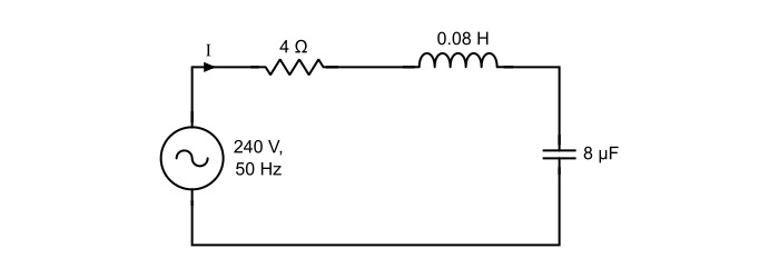
A 240 V, 50 Hz AC supply is applied a coil of 0.08 H inductance and 4 Ω resistance connected in series with a capacitor of 8 μF. Calculate the following −
- Impedance,
- Circuit current,
- Phase angle between voltage and current,
- Power factor,
- Power consumed,
- Q-factor of the circuit at resonant frequency.
Solution
Here,
$$\mathrm{\mathit{X}_{L}=\omega L=2\pi \mathit{fL}=2\pi×50×0.08=25.12 Ω}$$
$$\mathrm{\mathit{X}_{C}=\frac{1}{\omega C}=\frac{1}{2\pi \mathit{fL}}=\frac{1}{2\pi×50×8×10^{−6}}=398.09\:Ω}$$
Thus,
- Impedance of the circuit
$$\mathrm{Z=\sqrt{(\mathit{R})^{2}+(\mathit{X}_{L}-\mathit{X}_{C})^{2}}=\sqrt{(4)^{2}+(25.12−398.09)^{2}}=372.99\:Ω}$$
- Circuit current
$$\mathrm{\mathit{I}=\frac{\mathit{V}}{\mathit{Z}}=\frac{240}{372.99}=0.643\:A}$$
- Phase angle between voltage and current
$$\mathrm{\Phi=\tan^{-1}(\frac{X_{L}-X_{C}}{R})=\tan^{-1}(\frac{25.12-398.09}{4})=−89.38°}$$
The negative sing of phase angle shows that current is leading the voltage.
- Power Factor
$$\mathrm{cos\phi=\frac{R}{Z}=\frac{4}{372.99}=0.01072 (leading)}$$
- Power consumed
$$\mathrm{\mathit{P}=\mathit{VI}cos\Phi=240×0.643×0.01072=1.654\:W}$$
- Q-factor of circuit at series resonance
$$\mathrm{\mathit{Q}_{0}-\mathit{factor}=\frac{1}{\mathit{R}}\sqrt{\frac{\mathit{L}}{\mathit{C}}}=\frac{1}{\mathit{R}}\sqrt{\frac{0.08}{8×10^{−6}}}=25}$$

34K+ Views
