 Data Structure
 Networking
 RDBMS
RDBMS Operating System
 Java
Java MS Excel
 iOS
iOS HTML
HTML CSS
CSS Android
 Python
 C Programming
 C++
C++ C#
C# MongoDB
 MySQL
MySQL Javascript
 PHP
PHP
- Selected Reading
- UPSC IAS Exams Notes
- Developer's Best Practices
- Questions and Answers
- Effective Resume Writing
- HR Interview Questions
- Computer Glossary
- Who is Who
RTOS Introduction with Arduino
RTOS stands for Real Time Operating System. It is used to run multiple tasks concurrently, schedule them as required, and enable them to share resources. Now, while getting into the details of RTOS is out of the scope of this article, we will walk through an example that will give you a fair idea of RTOS. For now, you can just note that RTOS will help you perform multi-tasking within your Arduino, just like how the OS on your machine helps you run multiple tasks (like writing mails, listening to music, etc.) simultaneously.
Now, since we are concerned with microcontrollers, we will use FreeRTOS, which is RTOS for embedded devices. Basically, it is designed to be small enough to support microcontrollers. You can read more about FreeRTOS here: https://en.wikipedia.org/wiki/FreeRTOS
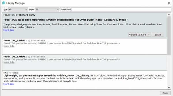
Now, to get started with FreeRTOS on Arduino, we will first need an external library. Go to Tools -> Manage Libraries and search for FreeRTOS.

You will see the library by Richard Barry. As mentioned, it works for Uno, Nano, Leonardo and Mega boards. We are using the Uno board, so we will install this library.
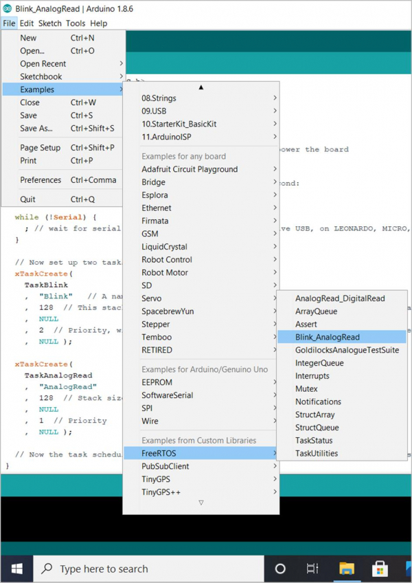
Now, once the library is installed, you will be able to see all the example codes related to this library in File -> Examples.

You are encouraged to go through all the examples to further understand FreeRTOS. We will walk through one of the examples: Blink_AnalogRead.
As you can see, we first include the library
#include <Arduino_FreeRTOS.h>
Later, we declare two tasks, Blink task and AnalogRead task.
void TaskBlink( void *pvParameters );
void TaskAnalogRead( void *pvParameters );
Note that this takes in pvParameters pointer as an input. We will come back to this later.
Next comes the important setup part.
Example
// the setup function runs once when you press reset or power the board
void setup() {
   // initialize serial communication at 9600 bits per second:
   Serial.begin(9600);
   while (!Serial) {
      ; // wait for serial port to connect. Needed for native USB, on LEONARDO, MICRO, YUN, and other 32u4 based boards.
   }
   // Now set up two tasks to run independently.
   xTaskCreate(
      TaskBlink
      ,   "Blink"    // A name just for humans
      ,   128   // This stack size can be checked & adjusted by reading the Stack Highwater
      ,   NULL
      ,   2   // Priority, with 3 (configMAX_PRIORITIES - 1) being the highest, and 0 being the lowest.
      ,   NULL );
   xTaskCreate(
      TaskAnalogRead
      ,   "AnalogRead"
      ,   128   // Stack size
      ,   NULL
      ,   1   // Priority
      ,   NULL
   );
   // Now the task scheduler, which takes over control of scheduling individual tasks, is automatically started.
}
Pay attention to all the comments in this part.
We first initialize serial and then wait for it to get initialized.
Then, we create the task using xTaskCreate. Now, xTaskCreate has the following syntax −
Syntax
BaseType_t xTaskCreate(TaskFunction_t pvTaskCode,const char * const pcName,configSTACK_DEPTH_TYPE usStackDepth,void *pvParameters, UBaseType_t uxPriority,TaskHandle_t *pxCreatedTask);
- pvTaskCode is the name of the function that executes the task (TaskBlink and TaskAnalogRead).
- pcName is the name of the task (as mentioned in the comments, just for human reference)
- usStackDepth is the number of words that are allocated to the task’s stack. Please refer to the datasheet of your board to determine how many bytes is equal to one word
- pvParameters are the parameters to be passed to the created task. You remember the pvParameters arguments at the time of declaring the tasks? These are where they come from. Say you want to pass in the number 1 to the task. You can do it by passing (void *) 1 to pvParameters argument of xTaskCreate
- uxPriority defines the priority of the task. Higher the number, more is the priority
- pxCreatedTask is the task handle. This is optional and you can pass in NULL. Its purpose is to reference the task in other parts of the code.
Once our tasks have been created, as mentioned in the comments, the task scheduler automatically gets started. Next, our loop is empty, since we are executing our code in tasks.
Finally, the functions for the two tasks are defined.
Example
void TaskBlink(void *pvParameters)   // This is a task.
{
   (void) pvParameters;

/*
   Blink
   Turns on an LED on for one second, then off for one second, repeatedly.
   Most Arduinos have an on-board LED you can control. On the UNO, LEONARDO, MEGA, and ZERO, it is attached to digital pin 13, on MKR1000 on pin 6. LED_BUILTIN takes care of use the correct LED pin whatever is the board used.
   The MICRO does not have a LED_BUILTIN available. For the MICRO board please substitute the LED_BUILTIN definition with either LED_BUILTIN_RX or LED_BUILTIN_TX. e.g. pinMode(LED_BUILTIN_RX, OUTPUT); etc.
   If you want to know what pin the on-board LED is connected to on your Arduino model, check the Technical Specs of your board at https://www.arduino.cc/en/Main/Products

   This example code is in the public domain.
   modified 8 May 2014
   by Scott Fitzgerald
   modified 2 Sep 2016
   by Arturo Guadalupi
*/

   // initialize digital LED_BUILTIN on pin 13 as an output.
   pinMode(LED_BUILTIN, OUTPUT);

   for (;;) // A Task shall never return or exit.
   {
      digitalWrite(LED_BUILTIN, HIGH);    // turn the LED on (HIGH is the voltage level)
      vTaskDelay( 1000 / portTICK_PERIOD_MS ); // wait for one second
      digitalWrite(LED_BUILTIN, LOW);      // turn the LED off by making the voltage LOW
      vTaskDelay( 1000 / portTICK_PERIOD_MS ); // wait for one second
   }
}

void TaskAnalogRead(void *pvParameters)   // This is a task.
{
   (void) pvParameters;

/*
   AnalogReadSerial
   Reads an analog input on pin 0, prints the result to the serial monitor.
   Graphical representation is available using serial plotter (Tools > Serial Plotter menu)
   Attach the center pin of a potentiometer to pin A0, and the outside pins to +5V and ground.
   This example code is in the public domain.
*/

   for (;;)
   {
      // read the input on analog pin 0:
      int sensorValue = analogRead(A0);
      // print out the value you read:
      Serial.println(sensorValue);
      vTaskDelay(1);   // one tick delay (15ms) in between reads for stability
   }
The comments within the tasks explain the code very well. Please note that within tasks, instead of delay(), we use vTaskDelay() within tasks. vTaskDelay(1) introduces a delay of 1 tick. Now, 1 tick may or may not correspond to 1ms. As mentioned in the comments of the AnalogRead task, 1 tick corresponds to 15ms. It depends on the clock frequency of the board. In order to get the delay time in ms, we can divide the time in ms with the portTICK_PERIOD_MS constant. As done in the TaskBlink, the delay of 1 second is realized with the following command: vTaskDelay( 1000 / portTICK_PERIOD_MS );
You can read more about freeRTOS here: https://www.freertos.org/

