
Article Categories
- All Categories
-
 Data Structure
-
 Networking
-
 RDBMS
RDBMS
-
 Operating System
-
 Java
Java
-
 MS Excel
-
 iOS
iOS
-
 HTML
HTML
-
 CSS
CSS
-
 Android
-
 Python
-
 C Programming
-
 C++
C++
-
 C#
C#
-
 MongoDB
-
 MySQL
MySQL
-
 Javascript
-
 PHP
PHP
-
 Economics & Finance
CAN Bus with Arduino
Communication protocols like UART (Serial), I2C and SPI are very popular because several peripherals can be interfaced with Arduino using these protocols. CAN (Controller Area Network) is another such protocol, which isn't very widely popular in general, but find several applications in the automotive domain.
While going into the details of CAN bus is beyond the scope of this article, you can find the relevant information here. However, here are a few things you should know −
CAN is a message-based protocol (i.e., the message and content are more important than the sender). A message transmitted by one device is received by all devices,including the transmitting device itself.
If multiple devices are transmitting at the same time, the device with the highest priority continues transmission, while others back off. Note that since CAN is a message based protocol, IDs are assigned to messages and not the devices.
It uses two lines for data transmission CAN_H and CAN_L. The differential voltage between these lines determines the signal. A positive difference above a threshold indicates a 1, while a negative voltage indicates a 0
The devices in the network are called nodes. CAN is very flexible in the sense that newer nodes can be added to the network, and nodes can be removed as well. All the nodes in the network only share two lines.
Data transmission happens in frames. Each data frame contains an 11 (base frame format) or 29 (extended frame format) identifier bits and 0 to 8 data bytes.
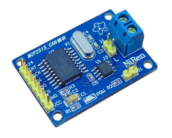
Now, Arduino Uno doesn't support CAN directly like it supports UART, SPI and I2C. Therefore, we will use external module, MCP2515 with TJA1050 transceiver, that interfaces with Arduino via SPI, and the transmits the message using CAN.
Circuit Diagram
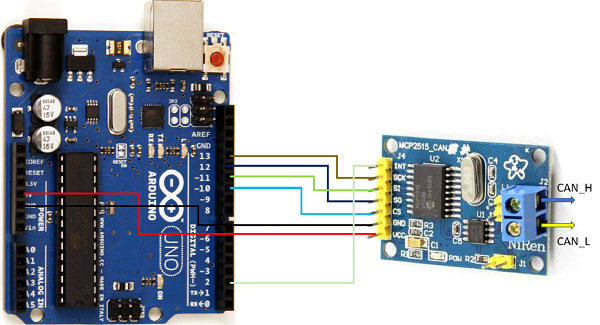
The Circuit Diagram for one node (transmitter) is shown below.
![]()
As you can see above, the Vcc line of the module is connected to 5V of Arduino, GND to GND,CS to pin 10, SO to pin 12 (MISO), SI to pin 11 (MOSI) and SCK to pin 13 (SCK).
On the receiving side, the connections are similar, except that the INT pin of the module is connected to pin 2 of Arduino.
The two (transmitter and receiver) are be joined together by CAN_H and CAN_L lines (CAN_H to CAN_H and CAN_L to CAN_L).
Library Required
We will use this library from Seeed Studio. This library won't be found in the Library Manager of Arduino. The procedure for downloading a third-party library is given here − https://www.tutorialspoint.com/using-a-third-party-library-in-arduino
Code Walkthrough
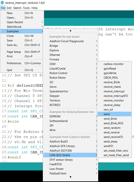
Once you have the library installed, you can find the send and receive_interrupt examples in File -> Examples -> CAN_BUS Shield.
We will be using slightly simplified versions of these examples.
The code for SEND is given below −
#include <SPI.h>
#include "mcp2515_can.h"
onst int SPI_CS_PIN = 10;
mcp2515_can CAN(SPI_CS_PIN); // Set CS pin
void setup() {
   Serial.begin(115200);
   while(!Serial){};
   // init can bus : baudrate = 500k
   while (CAN_OK != CAN.begin(CAN_500KBPS)) {
      Serial.println("CAN init fail, retry...");
      delay(100);
   }
   Serial.println("CAN init ok!");
}
unsigned char stmp[8] = {0, 0, 0, 0, 0, 0, 0, 0};
void loop() {
   // send data: id = 0x00, standrad frame, data len = 8, stmp: data buf
   stmp[7] = stmp[7] + 1;
   if (stmp[7] == 100) {
      stmp[7] = 0;
      stmp[6] = stmp[6] + 1;
      if (stmp[6] == 100) {
         stmp[6] = 0;
         stmp[5] = stmp[5] + 1;
      }
   }
   CAN.sendMsgBuf(0x00, 0, 8, stmp);
   delay(100); // send data per 100ms
   Serial.println("CAN BUS sendMsgBuf ok!");
}
Much of the code is self-explanatory. We will go through the implementation in brief.
We initialize CAN using the Chip Select pin (Pin 10 in our case).
mcp2515_can CAN(SPI_CS_PIN); // Set CS pin
We set the baud rate to 500 kbps in the Setup and check if CAN began properly.
CAN.begin(CAN_500KBPS))
We are transmitting 8 bytes in each frame to the received. The bytes are all 0 to begin with.Within loop, we keep incrementing the last byte, till it reaches 100, then add one to the second last byte and again keep incrementing the last byte till it reaches 100, and so on. We increment the third-last byte if the second-last byte reaches 100. This gives us several iterations to go on.
The important function is −
CAN.sendMsgBuf(0x00, 0, 8, stmp);
The first argument is the ID of the message (0x00), the second argument represents whether we are using the base format or the extended format (0 for base, and 1 for extended), the third argument is the length of the data (8), and the fourth is the data buffer.
This will keep sending 8-byte data frames to the receiver.
The code for RECEIVE is shown below −
#include <SPI.h>
#include "mcp2515_can.h"
const int SPI_CS_PIN = 10;
const int CAN_INT_PIN = 2;
mcp2515_can CAN(SPI_CS_PIN); // Set CS pin
unsigned char flagRecv = 0;
unsigned char len = 0;
unsigned char buf[8];
char str[20];
void setup() {
   Serial.begin(115200);
   while (!Serial) {
      ; // wait for serial port to connect. Needed for native USB port only
   }
   // start interrupt
   attachInterrupt(digitalPinToInterrupt(CAN_INT_PIN), MCP2515_ISR, FALLING);
   // init can bus : baudrate = 500k
   while (CAN_OK != CAN.begin(CAN_500KBPS)) {
      Serial.println("CAN init fail, retry...");
      delay(100);
   }
   Serial.println("CAN init ok!");
}
void MCP2515_ISR() {
   flagRecv = 1;
}
void loop() {
   if (flagRecv) {
      // check if get data
      flagRecv = 0; // clear flag
      Serial.println("into loop");
      // iterate over all pending messages
      // If either the bus is saturated or the MCU is busy,
      // both RX buffers may be in use and reading a single
      // message does not clear the IRQ conditon.
      while (CAN_MSGAVAIL == CAN.checkReceive()) {
         // read data, len: data length, buf: data buf
         Serial.println("checkReceive");
         CAN.readMsgBuf(&len, buf);
         // print the data
         for (int i = 0; i < len; i++) {
            Serial.print(buf[i]); Serial.print("\t");
         }
         Serial.println();
      }
   }
}
As you can see the initial variable declarations and the setup is similar to SEND. The only difference is that an interrupt is attached to digital pin 2. Remember that the INT pin of the module goes LOW whenever a message is received. Therefore, a FALLING EDGE interrupt is attached to pin 2, which is connected to the INT pin of the module.
// start interrupt
attachInterrupt(digitalPinToInterrupt(CAN_INT_PIN), MCP2515_ISR, FALLING);
Within the MCP2515_ISR function, we simply set the flagRecv to 1, which is checked inside the loop.
When the flagRecv value is 1, the available data in the CAN buffer is checked (using CAN.checkReceive()) and read and printed on the Serial Monitor. The function to read the data is −
CAN.readMsgBuf(&len, buf);
The first argument indicates the length of data available, and the second argument is the buffer to store the incoming data.
I hope you enjoyed this article. You are encouraged to go through the other examples that come in with this library.

13K+ Views
