
Article Categories
- All Categories
-
 Data Structure
-
 Networking
-
 RDBMS
RDBMS
-
 Operating System
-
 Java
Java
-
 MS Excel
-
 iOS
iOS
-
 HTML
HTML
-
 CSS
CSS
-
 Android
-
 Python
-
 C Programming
-
 C++
C++
-
 C#
C#
-
 MongoDB
-
 MySQL
MySQL
-
 Javascript
-
 PHP
PHP
-
 Economics & Finance
How to Control Common Bus in Computer Architecture?
A bus is a structure that handles the data transmission in a computer system or network. The common bus of 16-bit is controlled by the selection inputs S2, S1 , and, S0.
Each binary number is associated with a Boolean variable x1 through x7, corresponding to the gate structure that must be active to select the register or memory for the bus.
For example, when x1 = 1, the value of S2, S1 , and, S0 must be 001 and the output of AR will be selected for the bus.
The decimal number shown with each bus input indicates the binary equivalent that must be applied to the selection inputs. This is helpful while selecting the appropriate register.
The decimal number shown with each bus input indicates the binary equivalent that must be applied to the selection inputs. This is helpful while selecting the appropriate register.
The table shows the register that is to be chosen for the particular binary numbers of selection inputs.
| Inputs | Outputs | Register to be selected for bus | ||||||||
|---|---|---|---|---|---|---|---|---|---|---|
| X1 | X2 | X3 | X4 | X5 | X6 | X7 | S2 | S1 | S0 | |
| 0 | 0 | 0 | 0 | 0 | 0 | 0 | 0 | 0 | 0 | None |
| 1 | 1 | 1 | 1 | 1 | 1 | 1 | 0 | 0 | 0 | AR |
| 0 | 0 | 0 | 0 | 0 | 0 | 0 | 0 | 1 | 0 | PC |
| 0 | 0 | 0 | 0 | 0 | 0 | 0 | 0 | 1 | 0 | DR |
| 0 | 0 | 0 | 0 | 0 | 0 | 0 | 1 | 0 | 1 | AC |
| 0 | 0 | 0 | 0 | 0 | 0 | 0 | 1 | 0 | 1 | IR |
| 0 | 0 | 0 | 0 | 0 | 1 | 0 | 1 | 1 | 0 | TR |
| 0 | 0 | 0 | 0 | 0 | 0 | 1 | 1 | 1 | 1 | Memory |
Each of the binary numbers is related with a Boolean variable x1 through x7 in the figure.
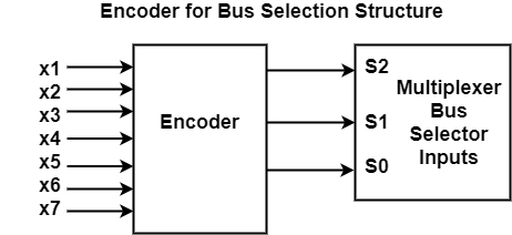
The encoder Boolean functions are as follows −
S0 = x1 + x3 + x5 + x7
S1 = x2 + x3 + x6 + x7
S1 = x4 + x5 + x6 + x7
The logic for each encoder input can be determined if control functions that place the corresponding register onto the bus, are found.

2K+ Views
