
Article Categories
- All Categories
-
 Data Structure
-
 Networking
-
 RDBMS
RDBMS
-
 Operating System
-
 Java
Java
-
 MS Excel
-
 iOS
iOS
-
 HTML
HTML
-
 CSS
CSS
-
 Android
-
 Python
-
 C Programming
-
 C++
C++
-
 C#
C#
-
 MongoDB
-
 MySQL
MySQL
-
 Javascript
-
 PHP
PHP
-
 Economics & Finance
Description of logic controller interface
We use a logic controller and it is used in industry for the process of control done by the software. Multiple inputs are typically accepted which performs a total complete sequence of operations carried out both arithmetic and logically. The outputs generated are used for the maintenance of the process within the specified desired limits. Visual display is provided by the state of process at any instant of time. The logic controller which interfaces and thus provides a buffered output of 12 lines and which is fed to the buffer inputs of 12 lines only specified for the user. The 12 output lines which are connected to the Ports A and C which is (lower) of 8255 on the ALS kit gets into action. The output lines status of 8255 gets displayed by using light emitting diodes (LED).
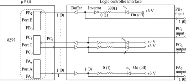
Values within parenthesis correspond to each other. Similarly, those outside parentheses correspond to each other. For example, if PB7 input is a1, the buffer output will also be a1, the inverter output will be 0, and the LED will be On.

471 Views
