
Article Categories
- All Categories
-
 Data Structure
-
 Networking
-
 RDBMS
RDBMS
-
 Operating System
-
 Java
Java
-
 MS Excel
-
 iOS
iOS
-
 HTML
HTML
-
 CSS
CSS
-
 Android
-
 Python
-
 C Programming
-
 C++
C++
-
 C#
C#
-
 MongoDB
-
 MySQL
MySQL
-
 Javascript
-
 PHP
PHP
-
 Economics & Finance
What is Logic Gates?
A logic gate is an electronic device that creates logical decisions depends on the various combinations of digital signals accessible on its inputs. A digital logic gate can have greater than one input signal but has only one digital output signal. There are seven basic logic gates such as AND, OR, XOR, NOT, NAND, NOR, and XNOR.
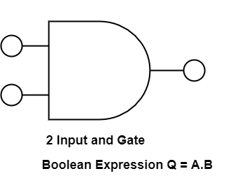
AND Gate
It is a digital logic gate. It has an output that is frequently at logic level “0” and goes “HIGH” to a logic level “1” when all of its inputs are at logic level “1”. The output of AND gate returns “LOW” when any of its inputs are at a logic level “0”.
The Boolean expression for AND gate is Q= A.B.
The diagram demonstrates the truth table and symbol of the AND gate.
Truth Table
| A | B | C |
|---|---|---|
| 0 | 0 | 0 |
| 1 | 0 | 0 |
| 0 | 1 | 0 |
| 1 | 1 | 1 |
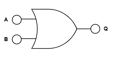
OR Gate
OR gate is also a digital logic gate that has an output that is frequently at logic level ’0’, but goes ’HIGH’ to a logic level ’1’ when any of its inputs are at logic level ’1’. The output of a logic OR gate returns ’LOW’ again when all of its inputs are at a logic level ’0’.
The Boolean expression for OR gate is indicated as Q = A+B.
The diagram demonstrates the truth table and symbol of the OR gate.
Truth Table
| A | B | C |
|---|---|---|
| 0 | 0 | 0 |
| 1 | 0 | 1 |
| 0 | 1 | 1 |
| 1 | 1 | 1 |
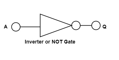
NOT Gate
In digital electronics, the NOT gate is also referred to as inverting buffer or a digital inverter element. A NOT gate is a single input device. It has an output level that is provided at logic level ‘1’. It goes ‘LOW’ to a logic level ‘0’ whenever the single input is at logic level ‘1’. The output from a NOT gate returns ’HIGH’ when its input is at logic level ’0’.
The Boolean expression of NOT gate is Q=A
The figure shows the truth table and symbol of NOT gate.
Truth Table
| A | Q |
|---|---|
| 0 | 1 |
| 1 | 0 |
Boolean Expression Q = not A or $\bar{A}$
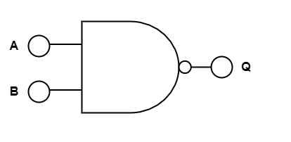
NAND Gate
NAND gate is a mixture of AND gate with an inverter or NOT gate linked in series. It has an output that is frequently at logic level ’1’ and only goes ’LOW’ to logic level ’0’ when all of its inputs are at logic level “1”.
The Boolean expression of the NAND gate is Q= $\bar{A.B}$
The diagram demonstrates the truth table and symbol of the NAND gate.
Truth Table
| A | B | Q |
|---|---|---|
| 0 | 0 | 1 |
| 1 | 0 | 1 |
| 0 | 1 | 1 |
| 1 | 1 | 0 |
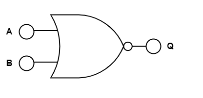
NOR Gate
NOR gate is a mixture of OR gate with a NOT gate linked in a series. The NOR gate has an output that is generally at logic level ’1’ and only goes ’LOW’ to logic level ’0’ when any of its inputs are at logic level ’1’.
The Boolean expression of NOR gate is Q= $\bar{A+B}$
The diagram demonstrates the truth table and symbol of the NOR gate.
Truth Table
| A | B | Q |
|---|---|---|
| 0 | 0 | 1 |
| 1 | 0 | 1 |
| 0 | 1 | 1 |
| 1 | 1 | 0 |
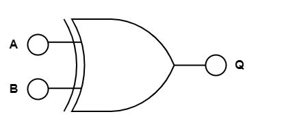
Exclusive-OR/ XOR GATE
It is a circuit that will give a high output if one of its inputs is high but not both of them. The XOR operation is defined by an encircled plus sign.
The Boolean expression is Q= (A$\oplus$B) = A.B+A.B
The diagram displays the truth table and symbol of the Exclusive-OR gate.
Truth Table
| A | B | Q |
|---|---|---|
| 0 | 0 | 0 |
| 1 | 0 | 1 |
| 0 | 1 | 1 |
| 1 | 1 | 0 |
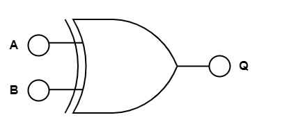
Exclusive-NOR Gate
The Exclusive-NOR gate function is a digital logic gate that is an interdependent form of the Exclusive-OR function. This function is at logic level ’1’, but it goes ’LOW’ to logic level ’0’ whenever any of its inputs are at logic level ’1’.
The Boolean expression is $\bar{Q}$ = (A$\oplus$$\bar{B}$) = A.B + A.B.
The figure shows the truth table and symbol of the Exclusive-NOR gate.
Truth Table
| A | B | Q |
|---|---|---|
| 0 | 0 | 1 |
| 1 | 0 | 0 |
| 0 | 1 | 0 |
| 1 | 1 | 1 |

2K+ Views
