 Data Structure
 Networking
 RDBMS
RDBMS Operating System
 Java
Java MS Excel
 iOS
iOS HTML
HTML CSS
CSS Android
 Python
 C Programming
 C++
C++ C#
C# MongoDB
 MySQL
MySQL Javascript
 PHP
PHP
- Selected Reading
- UPSC IAS Exams Notes
- Developer's Best Practices
- Questions and Answers
- Effective Resume Writing
- HR Interview Questions
- Computer Glossary
- Who is Who
What is Control Logic Gates?
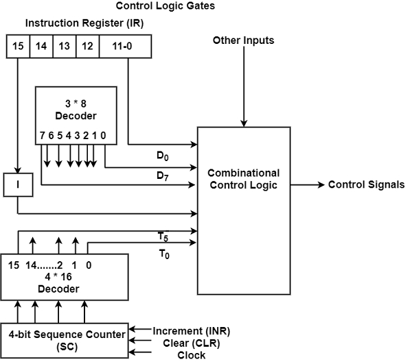
Control Logic Gates is the hardware component of a basic computer. It includes various inputs and outputs. The block diagram of the control logic gates is displayed in the figure. It includes two decoders, a sequence counter, and some control logic gates.

There are some instruction that is read from the memory is fixed in the Instruction Register (IR). Therefore, the IR is divided into three elements as I bit, opcode, and bits from 0 by 11. The opcodes are decoded with a 3 * 8 decoder whose outputs are indicated by symbols D0 through D7.
The binary value of the specific opcode is the subscripted number in the symbol. The symbol I which is the 15th bit of the instruction is transferred to a flip flop. The control logic gates have the bits that are used from 0 by 11. The sequence counter is 4-bit counts in binary from 0 by 15. It can be incremented or cleared synchronously. The timing signals from T0 through T15 are the decoded outputs of the decoder.
Input for Control Logic Circuit
The inputs for the control logic circuit are as follows −
- Two decoders.
- I flip-flop.
- 0 - 11 bits of the instruction register.
- 0-15 bits from AC to check if A=0 and to determine the sign bit.
- 0-15 bits from DR to check if DR=0 and the values of flip flops.
Output of Control Logic Circuit
The outputs for the control logic circuit are as follows −
- Signals controlling register inputs.
- Signals controlling the read/write inputs of memory.
- Signals framework, clearing, and complementing flip flops.
- Signals (S2, S1 , S0) selecting register for the bus.
- Signals controlling the AC adder/logic circuit.

