
Article Categories
- All Categories
-
 Data Structure
-
 Networking
-
 RDBMS
RDBMS
-
 Operating System
-
 Java
Java
-
 MS Excel
-
 iOS
iOS
-
 HTML
HTML
-
 CSS
CSS
-
 Android
-
 Python
-
 C Programming
-
 C++
C++
-
 C#
C#
-
 MongoDB
-
 MySQL
MySQL
-
 Javascript
-
 PHP
PHP
-
 Economics & Finance
Implementation of a Logic Function using OR and AND Gates
We can realize or implement a Boolean expression or a logic function as hardware using logic gates. The easiest method of implementing a logic function as hardware using logic gates is to start with the output and moves towards the inputs.
The implementation of a logic function with the help of logic gates involves connecting different logic gates in a specific manner. In this article, we shall confine our attention to implementing a logic function using the OR and AND gates only. Let's start the article with a brief introduction of OR and AND gates.
What is an OR Gate?
An OR Gate is a basic logic gate. An OR gate may accept two or more than two inputs, but gives only one output. The OR gate gives a HIGH (Logic 1) output if any one of its inputs is in the HIGH or Logic 1 state, otherwise, it gives a LOW (Logic 0) state as output. Therefore, the output of the OR gate is LOW or Logic 0 state, only if all its inputs are LOW or Logic 0 state.
The logic symbol of a two input OR gate is shown in Figure-1.

Here, A and B are the inputs to the OR gate and Y is the output of the OR gate, thus the output equation of the OR gate is given by,
$$\mathrm{Y=A+B}$$
Where, the ?+? symbol represents the OR operation. It is read as Y is equal to A OR B.
The operation of an OR gate for different combinations of inputs can be understood with the help of truth table. The following is the truth table for the OR Gate-
Input |
Output |
|
|---|---|---|
A |
B |
Y = A + B |
0 |
0 |
0 |
0 |
1 |
1 |
1 |
0 |
1 |
1 |
1 |
1 |
What is an AND Gate?
An AND Gate is a basic logic gate. An AND gate may have two or more than two inputs, but gives only one output. The AND gate gives a LOW (Logic 0) output if any one of its inputs is in the LOW or Logic 0 state, otherwise, it gives a HIGH (Logic 1) state as output. Therefore, the output of the AND gate is HIGH or Logic 1 state, only if all its inputs are HIGH or Logic 1 state.
The logic symbol of a two input AND gate is shown in Figure-2.

Here, A and B are the inputs and Y is the output variable of the AND gate, then the output equation of the AND gate is given by,
$$\mathrm{Y=A.B}$$
Where, the ?.? (dot) symbol represents the AND operation. It is read as Y is equal to A AND B.
The operation of an AND gate for different combinations of inputs can be understood with the help of truth table. The following is the truth table for a two input AND Gate ?
Input |
Output |
|
|---|---|---|
A |
B |
Y = A . B |
0 |
0 |
0 |
0 |
1 |
0 |
1 |
0 |
0 |
1 |
1 |
1 |
Now, let us discuss the implementation of a Boolean expression or logic function using OR and AND gates.
Implementation of a Logic Function using OR and AND Gates
In this section, we will understand the implementation of a logic function using OR and AND gates with the help of examples.
Example 1
Consider a logic function AB + A + ABC, we have to implement this Boolean expression using OR and AND gates. To realize this logic function, we will follow the following steps ?
Step 1 - Start with the final expression, i.e. output. We can see that there are three terms in the logic function. Hence, we require a three input OR gate for this.

Step 2 - As we can see, the first and third terms, i.e. AB and ABC of the logic function require AND operation. The term AB requires a two input AND gate, and the term ABC requires three input AND gate.

Step 3 - Finally, by combining the hardware realized in step-1 and setp-2, we get the complete hardware logic realization of the given logic function, which is shown in the following figure.
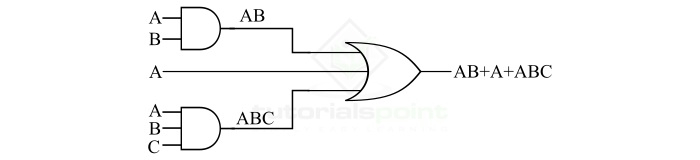
In this way, we can easily implement a logic function using OR and AND gates
Example 2
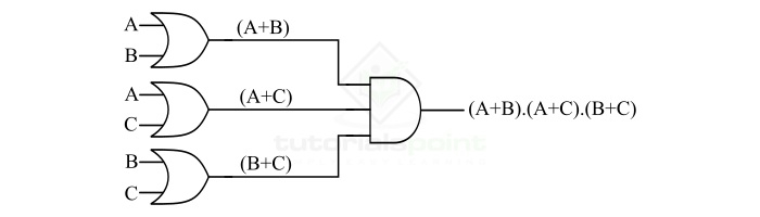
Consider another logic function (A+B).(A+C).(B+C), we have to implement this logic function using OR and AND gates only.
By observing this logical expression, we can interpret that we need a three input AND gate at the final output stage, and three two input OR gates to implement each of the three terms. Therefore, we can follow the following steps to implement the given logic function using OR and AND gates ?
Step 1 - Implement the final expression of the given logic function. As we can observe, we can implement it using a three-input AND gate as shown in the following figure.

Step 2 - Now, implement the three terms of the given logic function, i.e. (A+B), (A+C), (B+C), by using three two-input OR gates as shown in the following figure.

Step 3 - Finally, obtain the complete hardware realization of the given logic function by combining the logic circuits of the above two steps. The following figure shows the implementation of complement logic function using OR and AND gates.
Therefore, in the above two examples, we studied the process of implementation of a logic function using OR and AND gates.

2K+ Views
