
Article Categories
- All Categories
-
 Data Structure
-
 Networking
-
 RDBMS
RDBMS
-
 Operating System
-
 Java
Java
-
 MS Excel
-
 iOS
iOS
-
 HTML
HTML
-
 CSS
CSS
-
 Android
-
 Python
-
 C Programming
-
 C++
C++
-
 C#
C#
-
 MongoDB
-
 MySQL
MySQL
-
 Javascript
-
 PHP
PHP
-
 Economics & Finance
Implementation of Boolean Functions using Logic Gates
A Boolean function is a logical expression that returns a Boolean value, which is a value that is either TRUE or FALSE. In digital electronic circuits, the logic gates are used to implement a conditional or logical or Boolean expressions.
A logic gate is a digital circuit that performs a specific logical operation on one or more input variables or signals and generates an output signal. The output of a logic gate is determined by its logical function, which is based on Boolean algebra.
In digital electronics, there are several types of logic gates available such as AND gate, OR gate, NOT gate, NAND gate, NOR gate, XOR gate, XNOR gate, etc. we may use these logic gates to implement different types of Boolean functions.
Before going into the implementation of a Boolean function using logic gates, let's have a look into the basic introduction of different logic gates first.
What is an OR Gate?
An OR Gate is a basic logic gate. An OR gate may accept two or more than two inputs, but gives only one output. The OR gate gives a HIGH (Logic 1) output if any one of its inputs is in the HIGH or Logic 1 state, otherwise, it gives a LOW (Logic 0) state as output. Therefore, the output of the OR gate is LOW or Logic 0 state, only if all its inputs are LOW or Logic 0 state. The logic symbol of the OR gate is shown in Figure-1.

The expression of the output of the OR gate is given by,
$$\mathrm{Y = A + B + C + \cdot\cdot\cdot}$$
Where, A, B, C, ? are the input variables and Y is the output variable of the OR gate. The '+' symbol represents the OR operation.
What is an AND Gate?
An AND Gate is a basic logic gate. An AND gate may have two or more than two inputs, but gives only one output. The AND gate gives a LOW (Logic 0) output if any one of its inputs is in the LOW or Logic 0 state, otherwise, it gives a HIGH (Logic 1) state as output. Therefore, the output of the AND gate is HIGH or Logic 1 state, only if all its inputs are HIGH or Logic 1 state. The logic symbol of the AND gate is shown in Figure-2.

The expression of the output of the AND gate is given by
$$\mathrm{Y = A \cdot B \cdot C ...}$$
Where, the dot (.) symbol represents the AND operation.
What is a NOT Gate?
A NOT gate is a basic logic gate that has only one input and one output. It is type of logic gate whose output is always the complement of its input. Therefore, the NOT gate is also known as an inverter.
If the input of the NOT gate is LOW (or Logic 0), then it produces an output that is HIGH (Logic 1). If the input is HIGH (or Logic 1), then the NOT gate produces the LOW (Logic 0) output. The logic symbol of the NOT gate is shown in Figure-3.

The expression for the output of the NOT gate is given by,
$$\mathrm{Y = \bar{A} = A' }$$
Where, the bar (-) over the input variable represents the NOT operation.
Now, let us understand the implementation of Boolean functions using logic gates.
Implementation of Boolean Functions using Logic Gates
In this section, we will study the implementation of any type of Boolean function using logic gates. The easiest method to implement a Boolean function to a logic circuit is to start with the output and then work towards the inputs. Now, let us understand the complement processes through examples.
Implementation of Two Variable Boolean Function
Consider a Boolean function of two variables,
$$\mathrm{F = A\bar{B} + AB}$$
We have to implement this Boolean function using logic gates.
For implementing this Boolean function start with the final expression AB'+AB. Since, it is a summation of two terms, thus it must be the output of a two-input OR gate. So draw an OR gate with two inputs as shown in Figure-4.

Now, the term AB' is the output of a two input AND gate whose inputs are A and B'. Where, B' is in turn output of a NOT gate whose input is B. The term AB is the output of a two input AND gate whose inputs are A and B. Hence, the logic circuit will become as shown in Figure-5.
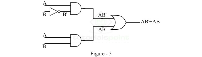
In this way, we can implement a two variable Boolean function using logic gates.
Implementation of Three Variable Boolean Function
Consider a three-variable Boolean function,
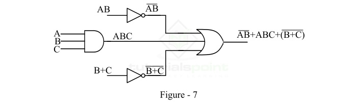
$$\mathrm{F = \overline{AB} + ABC +(\overline{B+C})}$$
We have to implement this Boolean function using logic gates.
We will start implement with the final expression $\mathrm{\overline{AB} + ABC +(\overline{B+C})}$. As we can see that it is a summation of three terms, hence it must be the output of a three-input OR gate. Therefore, we will draw an OR gate with three inputs as shown in Figure-6.

Here, the term $\mathrm{(\overline{AB})}$ must be the output of a NOT gate whose input is AB. The second term ABC must be the output of a three-input AND gate whose inputs are A, B, and C, and the third term $\mathrm{(\overline{B+C})}$ must be the output of a NOT gate whose input is B + C. Thus, we introduce two NOT gates and one AND gate in the logic circuit as shown in Figure-7.
Now, AB must be the output of a two-input AND gate whose inputs are A and B. And B + C must be the output of a two input OR gate whose inputs are B and C. So, we introduce an AND gate and an OR gate in the logic circuit as shown in Figure-8.
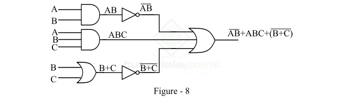
This is the complete implementation of the given Boolean function using logic gates. Hence, in this way, we can implement any Boolean function of any number of variables using logic gates.

12K+ Views
