
Article Categories
- All Categories
-
 Data Structure
-
 Networking
-
 RDBMS
RDBMS
-
 Operating System
-
 Java
Java
-
 MS Excel
-
 iOS
iOS
-
 HTML
HTML
-
 CSS
CSS
-
 Android
-
 Python
-
 C Programming
-
 C++
C++
-
 C#
C#
-
 MongoDB
-
 MySQL
MySQL
-
 Javascript
-
 PHP
PHP
-
 Economics & Finance
Reset_in* and Reset_out pins in 8085
Intel 8085 consists of a RESET_IN* pin which is an active low input pin. We RESET 8085 by placing a logic 0 on this pin at least for 0.5μs, after that the power is supplied to Vcc pin of 8085. Moreover, in practice we place the RESET_IN* in logic 0 state for a few milliseconds. A typical reset circuit which we use in ALS 8085 kit, is shown in the following Fig.
The moment when the power supply is switched on, the Vcc pin gets +5V power here the RESET_IN* pin stays in logic 0 state for a time dependency on the RC time constant. In the circuit in following Fig., the time constant RC is about 50ms. Hence the RESET_IN* pin remains in logic 0 for a longer time than the minimum time which is 0.5μs.
When we already power and the system is in running condition sometimes we need to reset the 8085. We do not need to switch off and on for 8085.
There are some actions which are performed by 8085 when we reset 8085.
The contents of the PC become 0000H.
The contents of the IR become 00H.
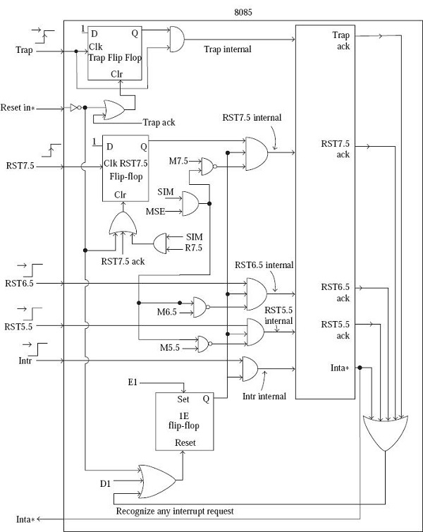
Except TRAP, all interrupts are disabled by resetting the flip-flop IE.

2K+ Views
