
Article Categories
- All Categories
-
 Data Structure
-
 Networking
-
 RDBMS
RDBMS
-
 Operating System
-
 Java
Java
-
 MS Excel
-
 iOS
iOS
-
 HTML
HTML
-
 CSS
CSS
-
 Android
-
 Python
-
 C Programming
-
 C++
C++
-
 C#
C#
-
 MongoDB
-
 MySQL
MySQL
-
 Javascript
-
 PHP
PHP
-
 Economics & Finance
EI and DI instructions in 8085
In 8085 is having five internal interrupt signals that correspond to the five external interrupt pins. And these interrupts are only recognized only when the internal interrupt signal is activated, the 8085 gets interrupted, provided higher priority internal interrupt signals are not active at the same time. The 8085 checks all these internal interrupt signals in the penultimate clock cycle of the last machine cycle of instruction.
With in 8085, there is a flip-flop called IE flip-flop. Here IE stands for Interrupt Enable. 8085 interrupt system is disabled whenever this flip-flop is reset to the 0 states. That is, even if an external interrupt pin is activated, the corresponding internal interrupt signal is not activated. It can be observed in the following diagram, which provides the internal architecture of the 8085 interrupt structure.
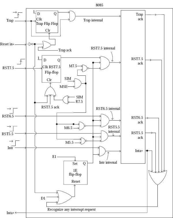
It is clear from the diagram that this flip-flop state has nothing to do with the internal interrupt signal corresponding toTRAP. TRAP is the highest priority, non-maskable interrupt. It means whenever the external TRAP pin is activated, the corresponding internal interrupt signal is always activated.
The IE flip-flop is reset to the 0 state by the following three conditions –
Execution of DI instruction;
Recognition of an interrupt request
Resetting of 8085.
The DI instruction stands for “Disable Interrupts”.It is a 1-Byte instruction. When this instruction is executed, the IE flip-flop is reset. This disables the 8085 interrupt system except for the TRAP pin.
When the 8085 recognizes an interrupt, it branches to an ISS (Interrupt Service Subroutine). By recognition, we mean that an internal interrupt signal is activated, and higher priority internal interrupt signals are not active. In the ISS, the 8085 would not like to be interrupted again. That is the reason, as to why the 8085 will place itself in DI state when it recognizes an interrupt. However, TRAP can still interrupt an ISS. Thus, when the control is transferred to an ISS, interrupt system is disabled automatically. Accordingly, there is no need for the programmer to write a DIinstruction at the beginning of an ISS. Whether the programmer writes a DI instruction at the beginning of an ISS or not, interrupt system remains disabled, except for TRAP.
| Mnemonics, Operand |
Opcode(in HEX) |
Bytes |
|---|---|---|
| EI |
FB |
1 |
| DI |
F3 |
1 |
Let us consider the following program segment –
| Address |
Hex Codes |
Mnemonic |
Comment |
|---|---|---|---|
| 2000 |
FB |
EI |
Enable Interrupt will make EI = 1 |
| 2001 |
F3 |
DI |
Disable Interrupt will make EI = 0 |
The timing diagram against this instruction EI execution is as follows –
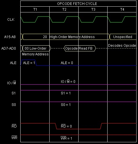
Summary − So this instruction EI requires 1-Byte, 1-Machine Cycle (Opcode Fetch) and 4 T-States for execution as shown in the timing diagram.
The timing diagram against this instruction DI execution is as follows –
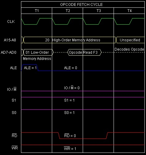
Summary − So this instruction DI requires 1-Byte, 1-Machine Cycle (Opcode Fetch) and 4 T-States for execution as shown in the timing diagram.

4K+ Views
