Practical Transformer on No-Load
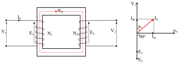
When the secondary winding of a practical transformer is open circuited, the transformer is said to be on no-load (see the figure). Under this condition, the primary winding will draw a small no-load current I0 from the source, which supplies the iron losses and a very small amount of copper loss in the core and primary winding respectively. Thus, the primary no-load current (I0) does not lag the applied voltage V1 by 90° but lags it by an angle φ0 which is less than 90°.

Therefore,
$$\mathrm{N_{o} \: - \: \text{ load input power, } \: P_{0} \: = \: V_{1} \: I_{0} \: \cos \: \varphi_{0}}$$
From the phasor diagram, it can be seen that the no-load primary current (I0) can be resolved into two rectangular components viz. active component and magnetising component.
Active Component
The component IW is in phase with the applied voltage V1 and is known as active component or iron loss component. This component of no-load current is responsible for supplying iron loss and a very small primary winding copper loss in the transformer. The IW is given by,
$$\mathrm{I_{W} \: = \: I_{0} \: \cos \: \varphi_{0}}$$
Magnetising Component
The component Im is lagging behind the applied voltage V1 by an angle of 90° and is known as magnetising component of the no-load current. The magnetising component is responsible for producing the mutual flux φm in the core of the transformer and is given by,
$$\mathrm{I_{m} \: = \: I_{0} \: \sin \: \varphi_{0}}$$
Therefore, the no-load current I0 is the phasor sum of IW and Im i.e.
$$\mathrm{I_{0} \: = \: \sqrt{I_{W}^{2} \: + \: I_{m}^{2}}}$$
Also, the no-load power factor is given by,
$$\mathrm{\cos \: \varphi_{0} \: = \: \frac{I_{W}}{I_{0}}}$$
It should be noted that, in a practical transformer the copper loss in primary winding at no-load is very small and may be neglected. Therefore, the input power at no-load in a practical transformer is equal to the iron losses in the core of the transformer i.e.
$$\mathrm{N_{o} \: - \: \text{ load input power, } \: P_{0} \: = \: \text{ Iron losses}}$$
Also, at no-load, there is no current flowing in the secondary winding. Hence, E2 = V2.
No-Load Equivalent Circuit of Practical Transformer
When the transformer is on no-load, no current flows in the secondary winding. Although, the primary winding draws a small no-load current (I0), which supplies the magnetising current (Im) to produce flux in the core and the current IW to supply the core losses. Therefore, the noload primary current is divided into two components and hence it can be represented by two parallel braches which composed of a parallel circuit R0 - Xm in parallel with the primary winding.
The resistance R0 is called core-loss resistance which represents the iron losses (i.e., hysteresis and eddy current losses), thus the current IW flows through the R0 branch. The inductive reactance Xm is known as magnetising reactance which represents a loss-less coil that produces the magnetic flux in the core, thus the magnetising current Im passes through it.

The core loss resistance (R0) is given by,
$$\mathrm{R_{0} \: = \: \frac{V_{1}}{I_{W}}}$$
The magnetising reactance (Xm) is given by,
$$\mathrm{X_{m} \: = \: \frac{V_{1}}{I_{m}}}$$
It should be noted that, in a practical transformer the current IW is very small as compared to current Im. Therefore, the no-load power factor (cosφ0) of a practical transformer is very small.
Numerical Example
A 240/2200 V transformer takes a no load current of 5 A and absorbs 200 W. If the resistance of the primary winding is 0.08 Ω. Determine the following −
- The core loss
- No-load power factor
- Active component of no-load current
- Magnetising current
Solution
The power absorbed by the transformer at no-load supplies the iron losses and primary winding copper loss. Thus,
$$\mathrm{\text{primary winding cu - loss } \: = \: I_{0}^{2}R_{1} \: = \: 5^{2} \: \times \: 0.08 \: = \: 2\:W}$$
The Core Losses −
$$\mathrm{\text{Core losses } \: = \: P_{0} \: - \: \text{ primary cu loss}}$$
$$\mathrm{\Rightarrow \: \text{ Core losses } \: = \: 200 \: - \: 2 \: = \: 198 \:W}$$
No-load Power Factor −
$$\mathrm{\cos \: \varphi_{0} \: = \: \frac{P_{0}}{V_{1}I_{0}} \: = \: \frac{200}{240 \: \times \: 5} \: = \: 0.167 \: (lagging)}$$
Active Component of No-load Current −
$$\mathrm{I_{W} \: = \: I_{0} \: \cos \: \varphi_{0} \: = \: 5 \: \times \: 0.167 \: = \: 0.835 A}$$
Magnetising Current −
$$\mathrm{I_{m} \: = \: \sqrt{I_{0}^{2} \: - \: I_{W}^{2}} \: = \: \sqrt{(5)^{2} \: - \: (0.835)^{2}} \: = \:4.93\:A}$$
