- Electrical Machines - Home
- Basic Concepts
- Electromechanical Energy Conversion
- Energy Stored in Magnetic Field
- Singly-Excited and Doubly Excited Systems
- Rotating Electrical Machines
- Electrical Machines Types
- Faraday’s Laws of Electromagnetic Induction
- Concept of Induced EMF
- Fleming's Left Hand and Right Hand Rules
- Transformers
- Electrical Transformer
- Construction of Transformer
- EMF Equation of Transformer
- Turns Ratio and Voltage Transformation Ratio
- Ideal Transformer
- Practical Transformer
- Ideal and Practical Transformers
- Transformer on DC
- Losses in a Transformer
- Efficiency of Transformer
- 3-Phase Transformer
- Types of Transformers
- More on Transformers
- Transformer Working Principle
- Single-Phase Transformer Working Principle
- 3-Phase Transformer Principle
- 3-Phase Induction Motor Torque-Slip
- 3-Phase Induction Motor Torque-Speed
- 3-Phase Transformer Harmonics
- Double-Star Connection (3-6 Phase)
- Double-delta Connection (3-6 Phase)
- Transformer Ratios
- Voltage Regulation
- Delta-Star Connection (3-Phase)
- Star-Delta Connection (3-Phase)
- Autotransformer Conversion
- Back-to-back Test (Sumpner's Test)
- Transformer Voltage Drop
- Autotransformer Output
- Open and Short Circuit Test
- 3-Phase Autotransformer
- Star-Star Connection
- 6-Phase Diametrical Connections
- Circuit Test (Three-Winding)
- Potential Transformer
- Transformers Parallel Operation
- Open Delta (V-V) Connection
- Autotransformer
- Current Transformer
- No-Load Current Wave
- Transformer Inrush Current
- Transformer Vector Groups
- 3 to 12-Phase Transformers
- Scott-T Transformer Connection
- Transformer kVA Rating
- Three-Winding Transformer
- Delta-Delta Connection Transformer
- Transformer DC Supply Issue
- Equivalent Circuit Transformer
- Simplified Equivalent Circuit of Transformer
- Transformer No-Load Condition
- Transformer Load Condition
- OTI WTI Transformer
- CVT Transformer
- Isolation vs Regular Transformer
- Dry vs Oil-Filled
- DC Machines
- Construction of DC Machines
- Types of DC Machines
- Working Principle of DC Generator
- EMF Equation of DC Generator
- Derivation of EMF Equation DC Generator
- Types of DC Generators
- Working Principle of DC Motor
- Back EMF in DC Motor
- Types of DC Motors
- Losses in DC Machines
- Applications of DC Machines
- More on DC Machines
- DC Generator
- DC Generator Armature Reaction
- DC Generator Commutator Action
- Stepper vs DC Motors
- DC Shunt Generators Critical Resistance
- DC Machines Commutation
- DC Motor Characteristics
- Synchronous Generator Working Principle
- DC Generator Characteristics
- DC Generator Demagnetizing & Cross-Magnetizing
- DC Motor Voltage & Power Equations
- DC Generator Efficiency
- Electric Breaking of DC Motors
- DC Motor Efficiency
- Four Quadrant Operation of DC Motors
- Open Circuit Characteristics of DC Generators
- Voltage Build-Up in Self-Excited DC Generators
- Types of Armature Winding in DC Machines
- Torque in DC Motors
- Swinburne’s Test of DC Machine
- Speed Control of DC Shunt Motor
- Speed Control of DC Series Motor
- DC Motor of Speed Regulation
- Hopkinson's Test
- Permanent Magnet DC Motor
- Permanent Magnet Stepper Motor
- DC Servo Motor Theory
- DC Series vs Shunt Motor
- BLDC Motor vs PMSM Motor
- Induction Motors
- Introduction to Induction Motor
- Single-Phase Induction Motor
- 3-Phase Induction Motor
- Construction of 3-Phase Induction Motor
- 3-Phase Induction Motor on Load
- Characteristics of 3-Phase Induction Motor
- Speed Regulation and Speed Control
- Methods of Starting 3-Phase Induction Motors
- More on Induction Motors
- 3-Phase Induction Motor Working Principle
- 3-Phase Induction Motor Rotor Parameters
- Double Cage Induction Motor Equivalent Circuit
- Induction Motor Equivalent Circuit Models
- Slip Ring vs Squirrel Cage Induction Motors
- Single-Cage vs Double-Cage Induction Motor
- Induction Motor Equivalent Circuits
- Induction Motor Crawling & Cogging
- Induction Motor Blocked Rotor Test
- Induction Motor Circle Diagram
- 3-Phase Induction Motors Applications
- 3-Phase Induction Motors Torque Ratios
- Induction Motors Power Flow Diagram & Losses
- Determining Induction Motor Efficiency
- Induction Motor Speed Control by Pole-Amplitude Modulation
- Induction Motor Inverted or Rotor Fed
- High Torque Cage Motors
- Double-Cage Induction Motor Torque-Slip Characteristics
- 3-Phase Induction Motors Starting Torque
- 3-phase Induction Motor - Rotor Resistance Starter
- 3-phase Induction Motor Running Torque
- 3-Phase Induction Motor - Rotating Magnetic Field
- Isolated Induction Generator
- Capacitor-Start Induction Motor
- Capacitor-Start Capacitor-Run Induction Motor
- Winding EMFs in 3-Phase Induction Motors
- Split-Phase Induction Motor
- Shaded Pole Induction Motor
- Repulsion-Start Induction-Run Motor
- Repulsion Induction Motor
- PSC Induction Motor
- Single-Phase Induction Motor Performance Analysis
- Linear Induction Motor
- Single-Phase Induction Motor Testing
- 3-Phase Induction Motor Fault Types
- Synchronous Machines
- Introduction to 3-Phase Synchronous Machines
- Construction of Synchronous Machine
- Working of 3-Phase Alternator
- Armature Reaction in Synchronous Machines
- Output Power of 3-Phase Alternator
- Losses and Efficiency of an Alternator
- Losses and Efficiency of 3-Phase Alternator
- Working of 3-Phase Synchronous Motor
- Equivalent Circuit and Power Factor of Synchronous Motor
- Power Developed by Synchronous Motor
- More on Synchronous Machines
- AC Motor Types
- Induction Generator (Asynchronous Generator)
- Synchronous Speed Slip of 3-Phase Induction Motor
- Armature Reaction in Alternator at Leading Power Factor
- Armature Reaction in Alternator at Lagging Power Factor
- Stationary Armature vs Rotating Field Alternator Advantages
- Synchronous Impedance Method for Voltage Regulation
- Saturated & Unsaturated Synchronous Reactance
- Synchronous Reactance & Impedance
- Significance of Short Circuit Ratio in Alternator
- Hunting Effect Alternator
- Hydrogen Cooling in Synchronous Generators
- Excitation System of Synchronous Machine
- Equivalent Circuit Phasor Diagram of Synchronous Generator
- EMF Equation of Synchronous Generator
- Cooling Methods for Synchronous Generators
- Assumptions in Synchronous Impedance Method
- Armature Reaction at Unity Power Factor
- Voltage Regulation of Alternator
- Synchronous Generator with Infinite Bus Operation
- Zero Power Factor of Synchronous Generator
- Short Circuit Ratio Calculation of Synchronous Machines
- Speed-Frequency Relationship in Alternator
- Pitch Factor in Alternator
- Max Reactive Power in Synchronous Generators
- Power Flow Equations for Synchronous Generator
- Potier Triangle for Voltage Regulation in Alternators
- Parallel Operation of Alternators
- Load Sharing in Parallel Alternators
- Slip Test on Synchronous Machine
- Constant Flux Linkage Theorem
- Blondel's Two Reaction Theory
- Synchronous Machine Oscillations
- Ampere Turn Method for Voltage Regulation
- Salient Pole Synchronous Machine Theory
- Synchronization by Synchroscope
- Synchronization by Synchronizing Lamp Method
- Sudden Short Circuit in 3-Phase Alternator
- Short Circuit Transient in Synchronous Machines
- Power-Angle of Salient Pole Machines
- Prime-Mover Governor Characteristics
- Power Input of Synchronous Generator
- Power Output of Synchronous Generator
- Power Developed by Salient Pole Motor
- Phasor Diagrams of Cylindrical Rotor Moto
- Synchronous Motor Excitation Voltage Determination
- Hunting Synchronous Motor
- Self-Starting Synchronous Motor
- Unidirectional Torque Production in Synchronous Motor
- Effect of Load Change on Synchronous Motor
- Field Excitation Effect on Synchronous Motor
- Output Power of Synchronous Motor
- Input Power of Synchronous Motor
- V Curves & Inverted V Curves of Synchronous Motor
- Torque in Synchronous Motor
- Construction of 3-Phase Synchronous Motor
- Synchronous Motor
- Synchronous Condenser
- Power Flow in Synchronous Motor
- Types of Faults in Alternator
- Miscellaneous Topics
- Electrical Generator
- Determining Electric Motor Load
- Solid State Motor Starters
- Characteristics of Single-Phase Motor
- Types of AC Generators
- Three-Point Starter
- Four-Point Starter
- Ward Leonard Speed Control Method
- Pole Changing Method
- Stator Voltage Control Method
- DOL Starter
- Star-Delta Starter
- Hysteresis Motor
- 2-Phase & 3-Phase AC Servo Motors
- Repulsion Motor
- Reluctance Motor
- Stepper Motor
- PCB Motor
- Single-Stack Variable Reluctance Stepper Motor
- Schrage Motor
- Hybrid Schrage Motor
- Multi-Stack Variable Reluctance Stepper Motor
- Universal Motor
- Step Angle in Stepper Motor
- Stepper Motor Torque-Pulse Rate Characteristics
- Distribution Factor
- Electrical Machines Basic Terms
- Synchronizing Torque Coefficient
- Synchronizing Power Coefficient
- Metadyne
- Motor Soft Starter
- CVT vs PT
- Metering CT vs Protection CT
- Stator and Rotor in Electrical Machines
- Electric Motor Winding
- Electric Motor
- Useful Resources
- Quick Guide
- Resources
- Discussion
Types of DC Motors
In practical DC motors, the magnetic field is produced by electromagnets rather than permanent magnets. DC motors are then classified based on the connection of field winding in the motor circuit. On this basis, DC motors are classified into the following two types −
Separately Excited DC Motors
Self-Excited DC Motors
Separately Excited DC Motor
A DC motor whose magnetic field winding is excited from an independent source of DC electric supply like a battery is called a separately excited DC motor. Figure-1 shows the connection diagram of a separately excited DC motor.
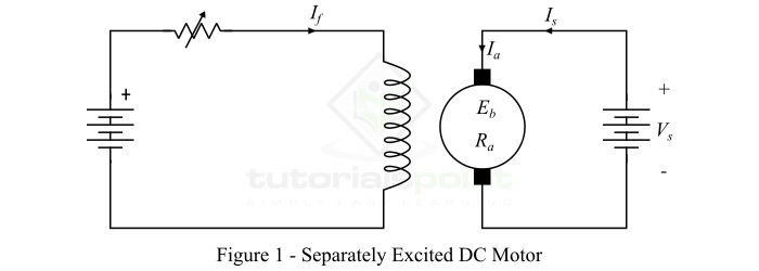
The speed of a separately excited DC motor depends upon the supply voltage and field current, i.e. magnetic flux in the machine. However, the separately excited DC motors are rarely used in practical applications because these require an external source of DC power for field excitation.
Self-Excited DC Motors
The type of DC motor whose magnetic field winding is excited from the same power supply from which the armature is supplied, is known as a self-excited DC motor.
Depending upon the manner in which the field winding is connected with the armature winding, self-excited DC motors are classified in the following three types −
Series DC motor
Shunt DC motor
Compound DC motor
Series DC Motor
A DC motor whose field winding is connected in series with the armature winding so that whole armature current passes through the field winding is called a series DC motor. Figure-2 shows the connection diagram of a series DC motor.
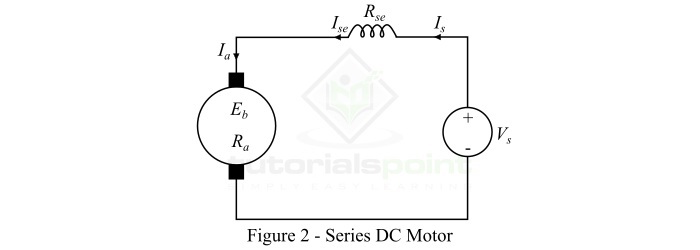
In case of a series DC motor, the field winding carries the whole armature current, thus it is made up of thick wire with less number of turns so that it possesses minimum resistance.
The following are some important expressions for the series DC motor −
$$\mathrm{\mathrm{Armature\:current},\mathit{I_{a}}\:=\:\mathit{I_{se}}\:=\:\mathit{I_{s}}}$$
Where, $\mathit{I_{se}}$ is the series field current and $\mathit{I_{s}}$ is the supply current.
$$\mathrm{\mathrm{Supply\:voltage},\mathit{V_{s}}\:=\:\mathit{E_{b}+I_{a}\left ( \mathit{R_{a}+R_{se}} \right )}}$$
Where, $\mathit{E_{b}}$ is the back EMF, $\mathit{R_{a}}$ is the armature circuit resistance, $\mathit{R_{se}}$ is the series field resistance.
Shunt DC Motor
A DC motor whose field winding is connected in parallel with the armature winding so that total supply voltage is applied across it, is known as a shunt DC motor. Figure-3 shows the connection diagram of a shunt DC motor.
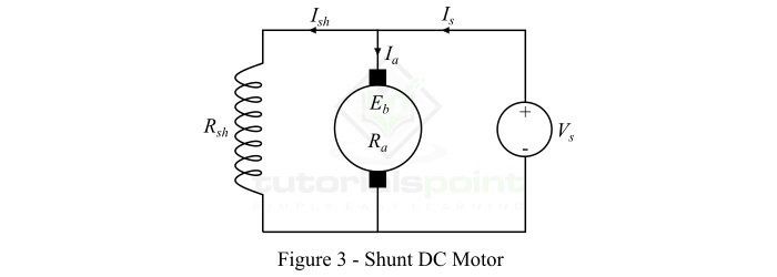
In a shunt DC motor, the shunt field winding has a large number of turns of thin wire so that it has high resistance, and therefore only a part of supply current flows through it and the rest flows through the armature winding.
Following are the important expressions of a shunt DC motor −
$$\mathrm{\mathrm{Armature\:current,}\mathit{I_{a}}\:=\:\mathit{I_{s}-I_{sh}}}$$
$$\mathrm{\mathrm{Shunt\:field\:current,}\mathit{I_{sh}}\:=\:\mathit{\frac{V_{s}}{R_{sh}}}}$$
$$\mathrm{\mathrm{Supply\:Voltage,}\mathit{V_{s}}\:=\:\mathit{E_{b}+I_{a}R_{a}}}$$
Compound DC Motor
A compound DC motor is one which has two sets of field windings on each magnetic pole one is in series and the other is in parallel with the armature winding.
Compound DC motors are sub-divided into the following two types −
Short-shunt compound DC motor
Long-shunt compound DC motor
A short-shunt compound DC motor is one in which only shunt field winding is in parallel with the armature winding as shown in Figure-4.
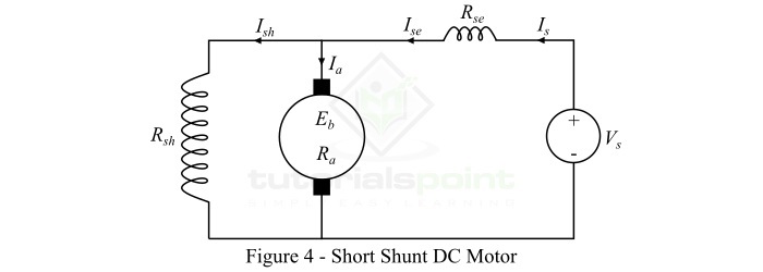
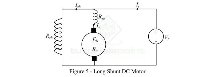
A long-shunt compound DC motor is one in which shunt field winding is in parallel with both series field winding and armature winding as shown in Figure-5.
The following are the important expressions for compound DC motors −
For short-shunt motor,
$$\mathrm{\mathrm{Armature\:current,}\mathit{I_{a}}\:=\:\mathit{I_{s}-I_{sh}}}$$
$$\mathrm{\mathrm{Series\:field\:current,}\mathit{I_{se}}\:=\:\mathit{I_{a}}}$$
$$\mathrm{\mathrm{Shunt\:field\:current,}\mathit{I_{sh}}\:=\:\frac{\mathit{V_{s}}-\mathit{I_{se}R_{se}}}{R_{sh}}}$$
$$\mathrm{\mathrm{Supply\:voltage},\mathit{V_{s}}\:=\:\mathit{E_{b}+I_{a}R_{a}+I_{se}R_{se}}}$$
For long-shunt motor,
$$\mathrm{\mathrm{Armature\:current,}\mathit{I_{a}}\:=\:\mathit{I_{s}-I_{sh}}}$$
$$\mathrm{\mathrm{Series\:field\:current,}\mathit{I_{se}}\:=\:\mathit{I_{s}}}$$
$$\mathrm{\mathrm{Shunt\:field\:current,}\mathit{I_{sh}}\:=\:\frac{\mathit{V_{s}}}{R_{sh}}}$$
$$\mathrm{\mathrm{Supply\:voltage},\mathit{V_{s}}\:=\:\mathit{E_{b}+I_{a}\left ( R_{a}+R_{se} \right )}}$$
