- Electrical Machines - Home
- Basic Concepts
- Electromechanical Energy Conversion
- Energy Stored in Magnetic Field
- Singly-Excited and Doubly Excited Systems
- Rotating Electrical Machines
- Electrical Machines Types
- Faraday’s Laws of Electromagnetic Induction
- Concept of Induced EMF
- Fleming's Left Hand and Right Hand Rules
- Transformers
- Electrical Transformer
- Construction of Transformer
- EMF Equation of Transformer
- Turns Ratio and Voltage Transformation Ratio
- Ideal Transformer
- Practical Transformer
- Ideal and Practical Transformers
- Transformer on DC
- Losses in a Transformer
- Efficiency of Transformer
- 3-Phase Transformer
- Types of Transformers
- More on Transformers
- Transformer Working Principle
- Single-Phase Transformer Working Principle
- 3-Phase Transformer Principle
- 3-Phase Induction Motor Torque-Slip
- 3-Phase Induction Motor Torque-Speed
- 3-Phase Transformer Harmonics
- Double-Star Connection (3-6 Phase)
- Double-delta Connection (3-6 Phase)
- Transformer Ratios
- Voltage Regulation
- Delta-Star Connection (3-Phase)
- Star-Delta Connection (3-Phase)
- Autotransformer Conversion
- Back-to-back Test (Sumpner's Test)
- Transformer Voltage Drop
- Autotransformer Output
- Open and Short Circuit Test
- 3-Phase Autotransformer
- Star-Star Connection
- 6-Phase Diametrical Connections
- Circuit Test (Three-Winding)
- Potential Transformer
- Transformers Parallel Operation
- Open Delta (V-V) Connection
- Autotransformer
- Current Transformer
- No-Load Current Wave
- Transformer Inrush Current
- Transformer Vector Groups
- 3 to 12-Phase Transformers
- Scott-T Transformer Connection
- Transformer kVA Rating
- Three-Winding Transformer
- Delta-Delta Connection Transformer
- Transformer DC Supply Issue
- Equivalent Circuit Transformer
- Simplified Equivalent Circuit of Transformer
- Transformer No-Load Condition
- Transformer Load Condition
- OTI WTI Transformer
- CVT Transformer
- Isolation vs Regular Transformer
- Dry vs Oil-Filled
- DC Machines
- Construction of DC Machines
- Types of DC Machines
- Working Principle of DC Generator
- EMF Equation of DC Generator
- Derivation of EMF Equation DC Generator
- Types of DC Generators
- Working Principle of DC Motor
- Back EMF in DC Motor
- Types of DC Motors
- Losses in DC Machines
- Applications of DC Machines
- More on DC Machines
- DC Generator
- DC Generator Armature Reaction
- DC Generator Commutator Action
- Stepper vs DC Motors
- DC Shunt Generators Critical Resistance
- DC Machines Commutation
- DC Motor Characteristics
- Synchronous Generator Working Principle
- DC Generator Characteristics
- DC Generator Demagnetizing & Cross-Magnetizing
- DC Motor Voltage & Power Equations
- DC Generator Efficiency
- Electric Breaking of DC Motors
- DC Motor Efficiency
- Four Quadrant Operation of DC Motors
- Open Circuit Characteristics of DC Generators
- Voltage Build-Up in Self-Excited DC Generators
- Types of Armature Winding in DC Machines
- Torque in DC Motors
- Swinburne’s Test of DC Machine
- Speed Control of DC Shunt Motor
- Speed Control of DC Series Motor
- DC Motor of Speed Regulation
- Hopkinson's Test
- Permanent Magnet DC Motor
- Permanent Magnet Stepper Motor
- DC Servo Motor Theory
- DC Series vs Shunt Motor
- BLDC Motor vs PMSM Motor
- Induction Motors
- Introduction to Induction Motor
- Single-Phase Induction Motor
- 3-Phase Induction Motor
- Construction of 3-Phase Induction Motor
- 3-Phase Induction Motor on Load
- Characteristics of 3-Phase Induction Motor
- Speed Regulation and Speed Control
- Methods of Starting 3-Phase Induction Motors
- More on Induction Motors
- 3-Phase Induction Motor Working Principle
- 3-Phase Induction Motor Rotor Parameters
- Double Cage Induction Motor Equivalent Circuit
- Induction Motor Equivalent Circuit Models
- Slip Ring vs Squirrel Cage Induction Motors
- Single-Cage vs Double-Cage Induction Motor
- Induction Motor Equivalent Circuits
- Induction Motor Crawling & Cogging
- Induction Motor Blocked Rotor Test
- Induction Motor Circle Diagram
- 3-Phase Induction Motors Applications
- 3-Phase Induction Motors Torque Ratios
- Induction Motors Power Flow Diagram & Losses
- Determining Induction Motor Efficiency
- Induction Motor Speed Control by Pole-Amplitude Modulation
- Induction Motor Inverted or Rotor Fed
- High Torque Cage Motors
- Double-Cage Induction Motor Torque-Slip Characteristics
- 3-Phase Induction Motors Starting Torque
- 3-phase Induction Motor - Rotor Resistance Starter
- 3-phase Induction Motor Running Torque
- 3-Phase Induction Motor - Rotating Magnetic Field
- Isolated Induction Generator
- Capacitor-Start Induction Motor
- Capacitor-Start Capacitor-Run Induction Motor
- Winding EMFs in 3-Phase Induction Motors
- Split-Phase Induction Motor
- Shaded Pole Induction Motor
- Repulsion-Start Induction-Run Motor
- Repulsion Induction Motor
- PSC Induction Motor
- Single-Phase Induction Motor Performance Analysis
- Linear Induction Motor
- Single-Phase Induction Motor Testing
- 3-Phase Induction Motor Fault Types
- Synchronous Machines
- Introduction to 3-Phase Synchronous Machines
- Construction of Synchronous Machine
- Working of 3-Phase Alternator
- Armature Reaction in Synchronous Machines
- Output Power of 3-Phase Alternator
- Losses and Efficiency of an Alternator
- Losses and Efficiency of 3-Phase Alternator
- Working of 3-Phase Synchronous Motor
- Equivalent Circuit and Power Factor of Synchronous Motor
- Power Developed by Synchronous Motor
- More on Synchronous Machines
- AC Motor Types
- Induction Generator (Asynchronous Generator)
- Synchronous Speed Slip of 3-Phase Induction Motor
- Armature Reaction in Alternator at Leading Power Factor
- Armature Reaction in Alternator at Lagging Power Factor
- Stationary Armature vs Rotating Field Alternator Advantages
- Synchronous Impedance Method for Voltage Regulation
- Saturated & Unsaturated Synchronous Reactance
- Synchronous Reactance & Impedance
- Significance of Short Circuit Ratio in Alternator
- Hunting Effect Alternator
- Hydrogen Cooling in Synchronous Generators
- Excitation System of Synchronous Machine
- Equivalent Circuit Phasor Diagram of Synchronous Generator
- EMF Equation of Synchronous Generator
- Cooling Methods for Synchronous Generators
- Assumptions in Synchronous Impedance Method
- Armature Reaction at Unity Power Factor
- Voltage Regulation of Alternator
- Synchronous Generator with Infinite Bus Operation
- Zero Power Factor of Synchronous Generator
- Short Circuit Ratio Calculation of Synchronous Machines
- Speed-Frequency Relationship in Alternator
- Pitch Factor in Alternator
- Max Reactive Power in Synchronous Generators
- Power Flow Equations for Synchronous Generator
- Potier Triangle for Voltage Regulation in Alternators
- Parallel Operation of Alternators
- Load Sharing in Parallel Alternators
- Slip Test on Synchronous Machine
- Constant Flux Linkage Theorem
- Blondel's Two Reaction Theory
- Synchronous Machine Oscillations
- Ampere Turn Method for Voltage Regulation
- Salient Pole Synchronous Machine Theory
- Synchronization by Synchroscope
- Synchronization by Synchronizing Lamp Method
- Sudden Short Circuit in 3-Phase Alternator
- Short Circuit Transient in Synchronous Machines
- Power-Angle of Salient Pole Machines
- Prime-Mover Governor Characteristics
- Power Input of Synchronous Generator
- Power Output of Synchronous Generator
- Power Developed by Salient Pole Motor
- Phasor Diagrams of Cylindrical Rotor Moto
- Synchronous Motor Excitation Voltage Determination
- Hunting Synchronous Motor
- Self-Starting Synchronous Motor
- Unidirectional Torque Production in Synchronous Motor
- Effect of Load Change on Synchronous Motor
- Field Excitation Effect on Synchronous Motor
- Output Power of Synchronous Motor
- Input Power of Synchronous Motor
- V Curves & Inverted V Curves of Synchronous Motor
- Torque in Synchronous Motor
- Construction of 3-Phase Synchronous Motor
- Synchronous Motor
- Synchronous Condenser
- Power Flow in Synchronous Motor
- Types of Faults in Alternator
- Miscellaneous Topics
- Electrical Generator
- Determining Electric Motor Load
- Solid State Motor Starters
- Characteristics of Single-Phase Motor
- Types of AC Generators
- Three-Point Starter
- Four-Point Starter
- Ward Leonard Speed Control Method
- Pole Changing Method
- Stator Voltage Control Method
- DOL Starter
- Star-Delta Starter
- Hysteresis Motor
- 2-Phase & 3-Phase AC Servo Motors
- Repulsion Motor
- Reluctance Motor
- Stepper Motor
- PCB Motor
- Single-Stack Variable Reluctance Stepper Motor
- Schrage Motor
- Hybrid Schrage Motor
- Multi-Stack Variable Reluctance Stepper Motor
- Universal Motor
- Step Angle in Stepper Motor
- Stepper Motor Torque-Pulse Rate Characteristics
- Distribution Factor
- Electrical Machines Basic Terms
- Synchronizing Torque Coefficient
- Synchronizing Power Coefficient
- Metadyne
- Motor Soft Starter
- CVT vs PT
- Metering CT vs Protection CT
- Stator and Rotor in Electrical Machines
- Electric Motor Winding
- Electric Motor
- Useful Resources
- Quick Guide
- Resources
- Discussion
Types of AC Generators
AC generators are commonly known as synchronous generators or alternators which convert mechanical power into AC power. The term alternator is used for AC generator because it produces AC power. Also, it is called synchronous generator because it must be driven at a constant speed (equal to synchronous speed) to generate AC power of the desired frequency.
In general, two types of AC generators are used in practice −
- Single Phase AC Generator
- Three Phase AC Generator
Single Phase AC Generator
A single phase AC generator is an electric machine that converts mechanical power into 1- phase electric power (AC) through the process of electromagnetic induction.
Construction of Single Phase AC Generator
A single phase AC generator has following main parts −
- Magnetic Field Systb
- Armature Core
- Armature Winding
- Yoke

Magnetic Field Systb
The magnetic field systb is used to produce uniform magnetic field in the single phase AC generator within which the armature rotates. The field systb may be composed of either permanent magnets (small generators) or electromagnets (in large generators). Generally, the field systb of a practical single phase AC generator consists of poles on which the field coils are mounted. When field coils are energised, a magnetic field produces within the generator.
Armature Core
The armature core is mounted on the machine shaft and rotates in the magnetic field of field poles. It consists of slotted soft iron laminations that are stacked to form a cylindrical core. The laminations are insulated from each other by a thin film of varnish. The core is made laminated to reduce the eddy current loss. The armature conductors are placed into the slots, made on the outer periphery of the armature core.
Armature Winding
The slots of the armature core hold insulated conductors, which are connected in a suitable manner. This is called as armature winding. This is the winding in which the working bF induces.
Yoke
The circular frame of the single phase AC generator is called yoke. The yoke of single phase AC generator is usually made of solid cast steel. The yoke increases the mechanical strength of the generator. It also provides path to the magnetic flux produced by the field winding.
Working of Single Phase AC Generator
Consider a simple loop single phase AC generator (as shown in the figure), in this a single turn loop ‘ABCD’ is rotating clockwise in a uniform magnetic field with a constant speed. When the loop rotates, the magnetic flux linking the coil sides ‘AB’ and ‘CD’ changes continuously. This change in flux linkage induces an bF in coil sides and the induced bF in one coil side adds the induced bF in the other.
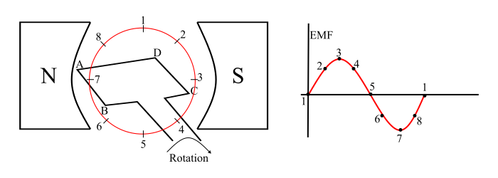
The bF induced in a single phase AC generator can be explained as follows −
- When the loop is in position-1, the generated bF is zero because, the movbent of coil sides is parallel to the magnetic flux.
- When the loop is in position-2, the coil sides are moving at an angle to the magnetic flux and hence, a small bF is generated.
- When the loop is in position-3, the coil sides are moving at right angle to the magnetic flux, therefore the generated bF is maximum
- When the loop is in position-4, the coil sides are cutting the magnetic flux at an angle, thus a reduced bF is generated in the coil sides.
- When the loop is in position-5, no flux linkage with the coil side and are moving parallel to the magnetic flux. Therefore, no bF is generated in the coil.
- At the position-6, the coil sides move under a pole of opposite polarity and hence the polarity of generated bF is reversed. The maximum bF will generate in this direction at position-7 and zero when at position-1. This cycle repeats with revolution of the coil.
In this way, the alternating bF is generated in a single phase AC generator, where the mechanical energy of rotation is converted into electrical energy.
Three Phase AC Generator
A three phase AC generator is a synchronous machine that coverts mechanical power into three-phase AC power through the process of electromagnetic induction.
A three phase AC generator or alternator operates on the principle of electromagnetic induction i.e. when the magnetic flux linking a conductor or coil changes, an bF is induced in the conductor or coil.
Important − A three phase AC generator has three identical armature windings displaced from each other by 120° electrical.
Construction of Three Phase AC Generator
A three phase AC generator has 3-phase winding on the stator and a field winding excited by DC supply on the rotor.
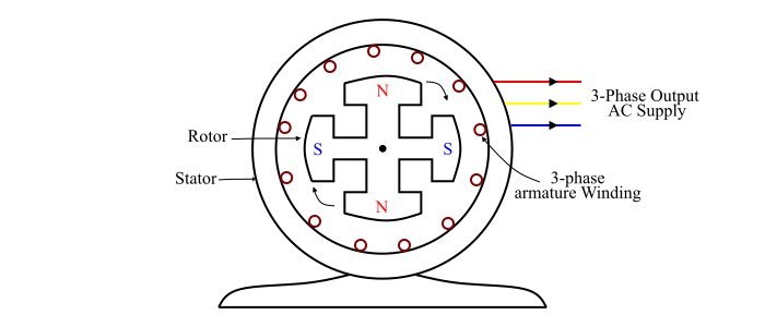
Stator
The stator is the stationary part of the three phase AC generator and is built of sheet-steel laminations having slots on its inner periphery. A three phase armature winding is placed in the stator slots of the generator. The armature winding of a three phase AC generator is always connected in star and the neutral is connected to the earth.
Rotor
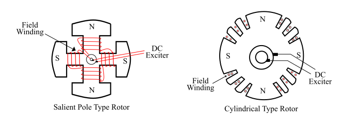
The rotor of a three phase AC generator carries a field winding which is supplied by a DC source (called exciter). The DC source is generally, a small DC shunt or compound generator mounted on the shaft of the three phase AC generator. There are two types of rotor constructions being used in a three phase AC generator −
- Salient Pole Type Rotor (Used in low and medium speed (120-400 RPM) alternators)
- Cylindrical Type Rotor (Used in high speed (1500-3000 RPM) alternators)
Operation of Three Phase AC Generator
The rotor winding of the three phase AC generator is connected to a DC exciter, so that alternate N and S poles are developed on the rotor. When the rotor is rotated in anti-clockwise direction by a prime mover, the armature conductors are cut by the rotating magnetic field of rotor poles.
Consequently, an bF is induced in the armature conductors due to electromagnetic induction. This induced bF in the armature is alternating one because N and S poles of rotor alternatively pass the armature conductors. The direction of the induced bF is given by Flbing’s right hand rule and the frequency is given by the equation,
$$\mathrm{f \: = \: \frac{N_{S}P}{120}\:\:HZ}$$
Where,
- NS = synchronous speed of rotating magnetic field = speed of rotor
- P = Number of rotor poles
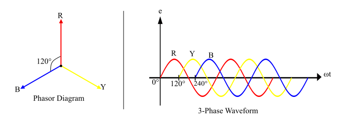
The magnitude of induced bF depends upon the speed of rotation and the DC excitation current. The magnitude of induced bF in each phase of the armature winding would be the same but displaced by 120° electrical from each other (see the waveform and phasor diagram).
The bF equation of a three phase AC generator is given by,
$$\mathrm{E_{RMS} / Phase \: = \: 2.22f \: \varphi \: Z \: Volts}$$
Since the armature winding of a three phase AC generator is star connected, thus the line voltage will be,
$$\mathrm{E_{L} \: = \: \sqrt{3} \: \times \: E_{ph}}$$
