- Electrical Machines - Home
- Basic Concepts
- Electromechanical Energy Conversion
- Energy Stored in Magnetic Field
- Singly-Excited and Doubly Excited Systems
- Rotating Electrical Machines
- Electrical Machines Types
- Faraday’s Laws of Electromagnetic Induction
- Concept of Induced EMF
- Fleming's Left Hand and Right Hand Rules
- Transformers
- Electrical Transformer
- Construction of Transformer
- EMF Equation of Transformer
- Turns Ratio and Voltage Transformation Ratio
- Ideal Transformer
- Practical Transformer
- Ideal and Practical Transformers
- Transformer on DC
- Losses in a Transformer
- Efficiency of Transformer
- 3-Phase Transformer
- Types of Transformers
- More on Transformers
- Transformer Working Principle
- Single-Phase Transformer Working Principle
- 3-Phase Transformer Principle
- 3-Phase Induction Motor Torque-Slip
- 3-Phase Induction Motor Torque-Speed
- 3-Phase Transformer Harmonics
- Double-Star Connection (3-6 Phase)
- Double-delta Connection (3-6 Phase)
- Transformer Ratios
- Voltage Regulation
- Delta-Star Connection (3-Phase)
- Star-Delta Connection (3-Phase)
- Autotransformer Conversion
- Back-to-back Test (Sumpner's Test)
- Transformer Voltage Drop
- Autotransformer Output
- Open and Short Circuit Test
- 3-Phase Autotransformer
- Star-Star Connection
- 6-Phase Diametrical Connections
- Circuit Test (Three-Winding)
- Potential Transformer
- Transformers Parallel Operation
- Open Delta (V-V) Connection
- Autotransformer
- Current Transformer
- No-Load Current Wave
- Transformer Inrush Current
- Transformer Vector Groups
- 3 to 12-Phase Transformers
- Scott-T Transformer Connection
- Transformer kVA Rating
- Three-Winding Transformer
- Delta-Delta Connection Transformer
- Transformer DC Supply Issue
- Equivalent Circuit Transformer
- Simplified Equivalent Circuit of Transformer
- Transformer No-Load Condition
- Transformer Load Condition
- OTI WTI Transformer
- CVT Transformer
- Isolation vs Regular Transformer
- Dry vs Oil-Filled
- DC Machines
- Construction of DC Machines
- Types of DC Machines
- Working Principle of DC Generator
- EMF Equation of DC Generator
- Derivation of EMF Equation DC Generator
- Types of DC Generators
- Working Principle of DC Motor
- Back EMF in DC Motor
- Types of DC Motors
- Losses in DC Machines
- Applications of DC Machines
- More on DC Machines
- DC Generator
- DC Generator Armature Reaction
- DC Generator Commutator Action
- Stepper vs DC Motors
- DC Shunt Generators Critical Resistance
- DC Machines Commutation
- DC Motor Characteristics
- Synchronous Generator Working Principle
- DC Generator Characteristics
- DC Generator Demagnetizing & Cross-Magnetizing
- DC Motor Voltage & Power Equations
- DC Generator Efficiency
- Electric Breaking of DC Motors
- DC Motor Efficiency
- Four Quadrant Operation of DC Motors
- Open Circuit Characteristics of DC Generators
- Voltage Build-Up in Self-Excited DC Generators
- Types of Armature Winding in DC Machines
- Torque in DC Motors
- Swinburne’s Test of DC Machine
- Speed Control of DC Shunt Motor
- Speed Control of DC Series Motor
- DC Motor of Speed Regulation
- Hopkinson's Test
- Permanent Magnet DC Motor
- Permanent Magnet Stepper Motor
- DC Servo Motor Theory
- DC Series vs Shunt Motor
- BLDC Motor vs PMSM Motor
- Induction Motors
- Introduction to Induction Motor
- Single-Phase Induction Motor
- 3-Phase Induction Motor
- Construction of 3-Phase Induction Motor
- 3-Phase Induction Motor on Load
- Characteristics of 3-Phase Induction Motor
- Speed Regulation and Speed Control
- Methods of Starting 3-Phase Induction Motors
- More on Induction Motors
- 3-Phase Induction Motor Working Principle
- 3-Phase Induction Motor Rotor Parameters
- Double Cage Induction Motor Equivalent Circuit
- Induction Motor Equivalent Circuit Models
- Slip Ring vs Squirrel Cage Induction Motors
- Single-Cage vs Double-Cage Induction Motor
- Induction Motor Equivalent Circuits
- Induction Motor Crawling & Cogging
- Induction Motor Blocked Rotor Test
- Induction Motor Circle Diagram
- 3-Phase Induction Motors Applications
- 3-Phase Induction Motors Torque Ratios
- Induction Motors Power Flow Diagram & Losses
- Determining Induction Motor Efficiency
- Induction Motor Speed Control by Pole-Amplitude Modulation
- Induction Motor Inverted or Rotor Fed
- High Torque Cage Motors
- Double-Cage Induction Motor Torque-Slip Characteristics
- 3-Phase Induction Motors Starting Torque
- 3-phase Induction Motor - Rotor Resistance Starter
- 3-phase Induction Motor Running Torque
- 3-Phase Induction Motor - Rotating Magnetic Field
- Isolated Induction Generator
- Capacitor-Start Induction Motor
- Capacitor-Start Capacitor-Run Induction Motor
- Winding EMFs in 3-Phase Induction Motors
- Split-Phase Induction Motor
- Shaded Pole Induction Motor
- Repulsion-Start Induction-Run Motor
- Repulsion Induction Motor
- PSC Induction Motor
- Single-Phase Induction Motor Performance Analysis
- Linear Induction Motor
- Single-Phase Induction Motor Testing
- 3-Phase Induction Motor Fault Types
- Synchronous Machines
- Introduction to 3-Phase Synchronous Machines
- Construction of Synchronous Machine
- Working of 3-Phase Alternator
- Armature Reaction in Synchronous Machines
- Output Power of 3-Phase Alternator
- Losses and Efficiency of an Alternator
- Losses and Efficiency of 3-Phase Alternator
- Working of 3-Phase Synchronous Motor
- Equivalent Circuit and Power Factor of Synchronous Motor
- Power Developed by Synchronous Motor
- More on Synchronous Machines
- AC Motor Types
- Induction Generator (Asynchronous Generator)
- Synchronous Speed Slip of 3-Phase Induction Motor
- Armature Reaction in Alternator at Leading Power Factor
- Armature Reaction in Alternator at Lagging Power Factor
- Stationary Armature vs Rotating Field Alternator Advantages
- Synchronous Impedance Method for Voltage Regulation
- Saturated & Unsaturated Synchronous Reactance
- Synchronous Reactance & Impedance
- Significance of Short Circuit Ratio in Alternator
- Hunting Effect Alternator
- Hydrogen Cooling in Synchronous Generators
- Excitation System of Synchronous Machine
- Equivalent Circuit Phasor Diagram of Synchronous Generator
- EMF Equation of Synchronous Generator
- Cooling Methods for Synchronous Generators
- Assumptions in Synchronous Impedance Method
- Armature Reaction at Unity Power Factor
- Voltage Regulation of Alternator
- Synchronous Generator with Infinite Bus Operation
- Zero Power Factor of Synchronous Generator
- Short Circuit Ratio Calculation of Synchronous Machines
- Speed-Frequency Relationship in Alternator
- Pitch Factor in Alternator
- Max Reactive Power in Synchronous Generators
- Power Flow Equations for Synchronous Generator
- Potier Triangle for Voltage Regulation in Alternators
- Parallel Operation of Alternators
- Load Sharing in Parallel Alternators
- Slip Test on Synchronous Machine
- Constant Flux Linkage Theorem
- Blondel's Two Reaction Theory
- Synchronous Machine Oscillations
- Ampere Turn Method for Voltage Regulation
- Salient Pole Synchronous Machine Theory
- Synchronization by Synchroscope
- Synchronization by Synchronizing Lamp Method
- Sudden Short Circuit in 3-Phase Alternator
- Short Circuit Transient in Synchronous Machines
- Power-Angle of Salient Pole Machines
- Prime-Mover Governor Characteristics
- Power Input of Synchronous Generator
- Power Output of Synchronous Generator
- Power Developed by Salient Pole Motor
- Phasor Diagrams of Cylindrical Rotor Moto
- Synchronous Motor Excitation Voltage Determination
- Hunting Synchronous Motor
- Self-Starting Synchronous Motor
- Unidirectional Torque Production in Synchronous Motor
- Effect of Load Change on Synchronous Motor
- Field Excitation Effect on Synchronous Motor
- Output Power of Synchronous Motor
- Input Power of Synchronous Motor
- V Curves & Inverted V Curves of Synchronous Motor
- Torque in Synchronous Motor
- Construction of 3-Phase Synchronous Motor
- Synchronous Motor
- Synchronous Condenser
- Power Flow in Synchronous Motor
- Types of Faults in Alternator
- Miscellaneous Topics
- Electrical Generator
- Determining Electric Motor Load
- Solid State Motor Starters
- Characteristics of Single-Phase Motor
- Types of AC Generators
- Three-Point Starter
- Four-Point Starter
- Ward Leonard Speed Control Method
- Pole Changing Method
- Stator Voltage Control Method
- DOL Starter
- Star-Delta Starter
- Hysteresis Motor
- 2-Phase & 3-Phase AC Servo Motors
- Repulsion Motor
- Reluctance Motor
- Stepper Motor
- PCB Motor
- Single-Stack Variable Reluctance Stepper Motor
- Schrage Motor
- Hybrid Schrage Motor
- Multi-Stack Variable Reluctance Stepper Motor
- Universal Motor
- Step Angle in Stepper Motor
- Stepper Motor Torque-Pulse Rate Characteristics
- Distribution Factor
- Electrical Machines Basic Terms
- Synchronizing Torque Coefficient
- Synchronizing Power Coefficient
- Metadyne
- Motor Soft Starter
- CVT vs PT
- Metering CT vs Protection CT
- Stator and Rotor in Electrical Machines
- Electric Motor Winding
- Electric Motor
- Useful Resources
- Quick Guide
- Resources
- Discussion
Power Output of Synchronous Generator or Alternator
The circuit model of a cylindrical rotor synchronous generator or alternator is shown in Figure-1.
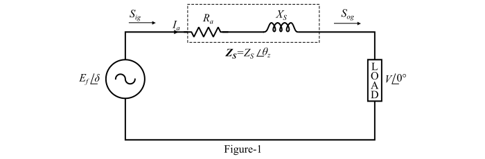
Let,
- V = Terminal voltage per phase
- Ef = Excitation voltage per phase
- Ia = Armature current
- δ = Load angle (between V and Ef )
By applying KVL in the circuit, we get,
$$\mathrm{E_{f} \:=\: V \:+\: I_{a}Z_{s} \:\:…\:\: (1)}$$
$$\mathrm{∴\:I_{a} \:=\:\frac{E_{f} \:−\: V}{Z_{s}}\:\:…\:\: (2)}$$
Where,
$$\mathrm{Synchronous\:impedance,\:Z_{s} \:=\: R_{a}\:+\: jX_{a} \:=\: Z_{}\:\angle _{z} \:\:…\:\: (3)}$$
Also, for a synchronous generator the excitation voltage ($E_{F}$) leads the terminal voltage (V) by the load angle (δ). Thus,
$$\mathrm{V \:=\: V \:\angle 0°\:\:then\:\:E_{f} \:=\: E_{f} \:\angle \delta}$$
Complex Power Output of the Alternator Per Phase
$$\mathrm{S_{og} \:=\: P_{og} \:+\: jQ_{og} \:=\:V{I^{*}_{a}}}$$
$$\mathrm{\Rightarrow\:S_{og} \:=\: V \left( \frac{E_{f} \:−\: V}{Z_{s}}\right)^{∗}\:=\:V\:\angle 0° \left(\frac{E_{F}\angle \delta − V \angle 0°}{Z_{} \angle _{z}} \right)^{∗}}$$
$$\mathrm{\Rightarrow\:S_{og} \:=\: V \:\angle 0° \left(\frac{E_{F}}{Z_{}}\:\angle(\delta \:−\: _{z}) \:−\: \frac{V}{Z_{}}\:\angle − _{z}\right)^{∗}\:=\:\frac{VE_{F}}{Z_{}}\:\angle(_{z} \:−\: \delta) \:−\:\frac{V^{2}}{Z_{}}\:\angle _{z}}$$
Therefore, the complex output power the synchronous generator is
$$\mathrm{S_{og} \:=\: P_{og} \:+\: jQ_{og}}$$
$$\mathrm{=\: \frac{VE_{F}}{Z_{}}cos(_{z} \:-\: \delta) \:+\: j\frac{VE_{F}}{Z_{}}sin(_{z} \:-\: \delta) \:- \:\frac{V^{2}}{Z_{}} \:(cos\:_{z} + j\:sin\:_{z }) \:\:…\:\: (4)}$$
Real Output Power Per Phase of the Alternator
Equating real parts of Eqn. (4), we get the real output power ($P_{og}$)
$$\mathrm{P_{og} \:=\:\frac{V{E_{F}} }{Z_{}}cos(_{z} \:−\: \delta) \:−\:\frac{V^{2}}{Z_{}}cos\:_{z}}$$

From the impedance triangle shown in Figure-2,
$$\mathrm{cos\:_{z}\:=\:\frac{R_{a}}{Z_{}}}$$
and
$$\mathrm{ _{z} \:=\: 90° \:− \:{α_{z}}}$$
$$\mathrm{∴\:\:P_{og}\: =\: \frac{VE_{F}}{Z_{}}cos(90° \:-\: \delta \:+\: α_{z}) \:- \:\frac{V^{2}}{Z^{2}_{}}R_{a}}$$
$$\mathrm{\Rightarrow\:P_{og} \:=\:\frac{VE_{F}}{Z_{}}sin(\delta \:+\: α_{z}) \: -\:\frac{V^{2}}{Z^{2}_{}}R_{a} \:\:…\:\: (5)}$$
The power ($P_{og}$) is also known as electrical power developed by the alternator.
Reactive Output Power Per Phase of the Alternator
Equating imaginary parts of the eq. (4), we get the reactive output power($Q_{og}$)
$$\mathrm{Q_{og} \:=\:\frac{VE_{F}}{Z_{}}(_{z} \:-\: \delta) \:−\:\frac{V^{2}}{Z_{}}sin\:_{z}}$$
From the impedance triangle shown in Figure-2, we get,
$$\mathrm{sin\:_{z} \:=\:\frac{X_{}}{Z_{}}}$$
and
$$\mathrm{_{z} \:=\: 90° \:−\: α_{z}}$$
$$\mathrm{∴\:Q_{og} \:=\:\frac{VE_{F}}{Z_{}}sin(90° \:-\: \delta \:+\: α_{z} )\:−\:\frac{V^{2}}{Z^{2}_{}}X_{ }}$$
$$\mathrm{\Rightarrow\:Q_{og} \:=\:\frac{VE_{F}}{Z_{}}cos(\delta \:+ \:α_{z})\:−\:\frac{V^{2}}{Z^{2}_{}}X_{ } \:\:…\:\: (6)}$$
Condition for Maximum Power Output of the Alternator Per Phase
For maximum power output of the alternator,
$$\mathrm{\frac{P_{og}}{}\:=\: 0\:\:and\:\:\frac{^{2}P_{og}}{{\delta}^{2}} \:<\: 0}$$
Therefore,
$$\mathrm{\frac{}{\delta}\left[\frac{VE_{F}}{Z_{}}sin(\delta \:+ \:α_{z})\:-\:\frac{V^{2}}{Z^{2}_{}}R_{a} \right] \:=\: 0}$$
$$\mathrm{\Rightarrow\:\frac{VE_{F}}{Z_{}}cos(\delta \:+\: α_{z})\:-\:0 \:=\: 0}$$
$$\mathrm{\Rightarrow\: cos(\delta \:+\:α_{z}) \:=\: 0}$$
$$\mathrm{\Rightarrow\:\delta \:+\: α_{z} \:=\: 90°}$$
$$\mathrm{\Rightarrow\:\delta \:=\: 90° \:-\: α_{z} \:=\: _{z} \:\:…\:\: (7)}$$
Hence for maximum power output of the alternator,
$$\mathrm{Load\:angle() \:=\: Impedance \:angle(_{z})}$$
Thus, from Eqns. (5) and (7), the maximum power output of the alternator is given by,
$$\mathrm{P_{og(a)} \:=\:\frac{VE_{F}}{Z_{}} \:-\:\frac{V^{2}}{Z^{2}_{}}R_{a}\:\:…\:\: (8)}$$
