- Electrical Machines - Home
- Basic Concepts
- Electromechanical Energy Conversion
- Energy Stored in Magnetic Field
- Singly-Excited and Doubly Excited Systems
- Rotating Electrical Machines
- Electrical Machines Types
- Faraday’s Laws of Electromagnetic Induction
- Concept of Induced EMF
- Fleming's Left Hand and Right Hand Rules
- Transformers
- Electrical Transformer
- Construction of Transformer
- EMF Equation of Transformer
- Turns Ratio and Voltage Transformation Ratio
- Ideal Transformer
- Practical Transformer
- Ideal and Practical Transformers
- Transformer on DC
- Losses in a Transformer
- Efficiency of Transformer
- 3-Phase Transformer
- Types of Transformers
- More on Transformers
- Transformer Working Principle
- Single-Phase Transformer Working Principle
- 3-Phase Transformer Principle
- 3-Phase Induction Motor Torque-Slip
- 3-Phase Induction Motor Torque-Speed
- 3-Phase Transformer Harmonics
- Double-Star Connection (3-6 Phase)
- Double-delta Connection (3-6 Phase)
- Transformer Ratios
- Voltage Regulation
- Delta-Star Connection (3-Phase)
- Star-Delta Connection (3-Phase)
- Autotransformer Conversion
- Back-to-back Test (Sumpner's Test)
- Transformer Voltage Drop
- Autotransformer Output
- Open and Short Circuit Test
- 3-Phase Autotransformer
- Star-Star Connection
- 6-Phase Diametrical Connections
- Circuit Test (Three-Winding)
- Potential Transformer
- Transformers Parallel Operation
- Open Delta (V-V) Connection
- Autotransformer
- Current Transformer
- No-Load Current Wave
- Transformer Inrush Current
- Transformer Vector Groups
- 3 to 12-Phase Transformers
- Scott-T Transformer Connection
- Transformer kVA Rating
- Three-Winding Transformer
- Delta-Delta Connection Transformer
- Transformer DC Supply Issue
- Equivalent Circuit Transformer
- Simplified Equivalent Circuit of Transformer
- Transformer No-Load Condition
- Transformer Load Condition
- OTI WTI Transformer
- CVT Transformer
- Isolation vs Regular Transformer
- Dry vs Oil-Filled
- DC Machines
- Construction of DC Machines
- Types of DC Machines
- Working Principle of DC Generator
- EMF Equation of DC Generator
- Derivation of EMF Equation DC Generator
- Types of DC Generators
- Working Principle of DC Motor
- Back EMF in DC Motor
- Types of DC Motors
- Losses in DC Machines
- Applications of DC Machines
- More on DC Machines
- DC Generator
- DC Generator Armature Reaction
- DC Generator Commutator Action
- Stepper vs DC Motors
- DC Shunt Generators Critical Resistance
- DC Machines Commutation
- DC Motor Characteristics
- Synchronous Generator Working Principle
- DC Generator Characteristics
- DC Generator Demagnetizing & Cross-Magnetizing
- DC Motor Voltage & Power Equations
- DC Generator Efficiency
- Electric Breaking of DC Motors
- DC Motor Efficiency
- Four Quadrant Operation of DC Motors
- Open Circuit Characteristics of DC Generators
- Voltage Build-Up in Self-Excited DC Generators
- Types of Armature Winding in DC Machines
- Torque in DC Motors
- Swinburne’s Test of DC Machine
- Speed Control of DC Shunt Motor
- Speed Control of DC Series Motor
- DC Motor of Speed Regulation
- Hopkinson's Test
- Permanent Magnet DC Motor
- Permanent Magnet Stepper Motor
- DC Servo Motor Theory
- DC Series vs Shunt Motor
- BLDC Motor vs PMSM Motor
- Induction Motors
- Introduction to Induction Motor
- Single-Phase Induction Motor
- 3-Phase Induction Motor
- Construction of 3-Phase Induction Motor
- 3-Phase Induction Motor on Load
- Characteristics of 3-Phase Induction Motor
- Speed Regulation and Speed Control
- Methods of Starting 3-Phase Induction Motors
- More on Induction Motors
- 3-Phase Induction Motor Working Principle
- 3-Phase Induction Motor Rotor Parameters
- Double Cage Induction Motor Equivalent Circuit
- Induction Motor Equivalent Circuit Models
- Slip Ring vs Squirrel Cage Induction Motors
- Single-Cage vs Double-Cage Induction Motor
- Induction Motor Equivalent Circuits
- Induction Motor Crawling & Cogging
- Induction Motor Blocked Rotor Test
- Induction Motor Circle Diagram
- 3-Phase Induction Motors Applications
- 3-Phase Induction Motors Torque Ratios
- Induction Motors Power Flow Diagram & Losses
- Determining Induction Motor Efficiency
- Induction Motor Speed Control by Pole-Amplitude Modulation
- Induction Motor Inverted or Rotor Fed
- High Torque Cage Motors
- Double-Cage Induction Motor Torque-Slip Characteristics
- 3-Phase Induction Motors Starting Torque
- 3-phase Induction Motor - Rotor Resistance Starter
- 3-phase Induction Motor Running Torque
- 3-Phase Induction Motor - Rotating Magnetic Field
- Isolated Induction Generator
- Capacitor-Start Induction Motor
- Capacitor-Start Capacitor-Run Induction Motor
- Winding EMFs in 3-Phase Induction Motors
- Split-Phase Induction Motor
- Shaded Pole Induction Motor
- Repulsion-Start Induction-Run Motor
- Repulsion Induction Motor
- PSC Induction Motor
- Single-Phase Induction Motor Performance Analysis
- Linear Induction Motor
- Single-Phase Induction Motor Testing
- 3-Phase Induction Motor Fault Types
- Synchronous Machines
- Introduction to 3-Phase Synchronous Machines
- Construction of Synchronous Machine
- Working of 3-Phase Alternator
- Armature Reaction in Synchronous Machines
- Output Power of 3-Phase Alternator
- Losses and Efficiency of an Alternator
- Losses and Efficiency of 3-Phase Alternator
- Working of 3-Phase Synchronous Motor
- Equivalent Circuit and Power Factor of Synchronous Motor
- Power Developed by Synchronous Motor
- More on Synchronous Machines
- AC Motor Types
- Induction Generator (Asynchronous Generator)
- Synchronous Speed Slip of 3-Phase Induction Motor
- Armature Reaction in Alternator at Leading Power Factor
- Armature Reaction in Alternator at Lagging Power Factor
- Stationary Armature vs Rotating Field Alternator Advantages
- Synchronous Impedance Method for Voltage Regulation
- Saturated & Unsaturated Synchronous Reactance
- Synchronous Reactance & Impedance
- Significance of Short Circuit Ratio in Alternator
- Hunting Effect Alternator
- Hydrogen Cooling in Synchronous Generators
- Excitation System of Synchronous Machine
- Equivalent Circuit Phasor Diagram of Synchronous Generator
- EMF Equation of Synchronous Generator
- Cooling Methods for Synchronous Generators
- Assumptions in Synchronous Impedance Method
- Armature Reaction at Unity Power Factor
- Voltage Regulation of Alternator
- Synchronous Generator with Infinite Bus Operation
- Zero Power Factor of Synchronous Generator
- Short Circuit Ratio Calculation of Synchronous Machines
- Speed-Frequency Relationship in Alternator
- Pitch Factor in Alternator
- Max Reactive Power in Synchronous Generators
- Power Flow Equations for Synchronous Generator
- Potier Triangle for Voltage Regulation in Alternators
- Parallel Operation of Alternators
- Load Sharing in Parallel Alternators
- Slip Test on Synchronous Machine
- Constant Flux Linkage Theorem
- Blondel's Two Reaction Theory
- Synchronous Machine Oscillations
- Ampere Turn Method for Voltage Regulation
- Salient Pole Synchronous Machine Theory
- Synchronization by Synchroscope
- Synchronization by Synchronizing Lamp Method
- Sudden Short Circuit in 3-Phase Alternator
- Short Circuit Transient in Synchronous Machines
- Power-Angle of Salient Pole Machines
- Prime-Mover Governor Characteristics
- Power Input of Synchronous Generator
- Power Output of Synchronous Generator
- Power Developed by Salient Pole Motor
- Phasor Diagrams of Cylindrical Rotor Moto
- Synchronous Motor Excitation Voltage Determination
- Hunting Synchronous Motor
- Self-Starting Synchronous Motor
- Unidirectional Torque Production in Synchronous Motor
- Effect of Load Change on Synchronous Motor
- Field Excitation Effect on Synchronous Motor
- Output Power of Synchronous Motor
- Input Power of Synchronous Motor
- V Curves & Inverted V Curves of Synchronous Motor
- Torque in Synchronous Motor
- Construction of 3-Phase Synchronous Motor
- Synchronous Motor
- Synchronous Condenser
- Power Flow in Synchronous Motor
- Types of Faults in Alternator
- Miscellaneous Topics
- Electrical Generator
- Determining Electric Motor Load
- Solid State Motor Starters
- Characteristics of Single-Phase Motor
- Types of AC Generators
- Three-Point Starter
- Four-Point Starter
- Ward Leonard Speed Control Method
- Pole Changing Method
- Stator Voltage Control Method
- DOL Starter
- Star-Delta Starter
- Hysteresis Motor
- 2-Phase & 3-Phase AC Servo Motors
- Repulsion Motor
- Reluctance Motor
- Stepper Motor
- PCB Motor
- Single-Stack Variable Reluctance Stepper Motor
- Schrage Motor
- Hybrid Schrage Motor
- Multi-Stack Variable Reluctance Stepper Motor
- Universal Motor
- Step Angle in Stepper Motor
- Stepper Motor Torque-Pulse Rate Characteristics
- Distribution Factor
- Electrical Machines Basic Terms
- Synchronizing Torque Coefficient
- Synchronizing Power Coefficient
- Metadyne
- Motor Soft Starter
- CVT vs PT
- Metering CT vs Protection CT
- Stator and Rotor in Electrical Machines
- Electric Motor Winding
- Electric Motor
- Useful Resources
- Quick Guide
- Resources
- Discussion
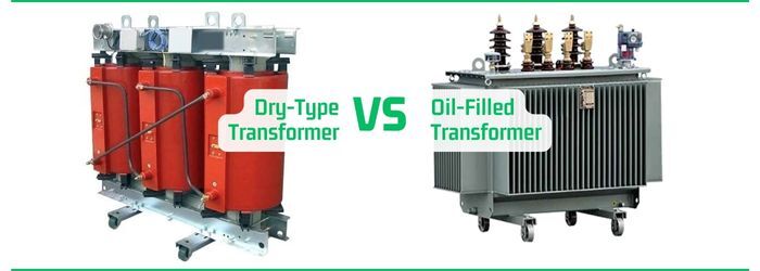
Difference between Dry-Type and Oil-Filled Transformers
The most fundamental difference between dry-type and oil-filled transformer is that a dry-type transformer has a solid insulating material to provide insulation between conducting parts of the transformer, whereas an oil-filled transformer is one in which dielectric oil is used as the insulating medium.
Both transformers have their own advantages, disadvantages, and applications. In this article, we will learn about the major differences between dry-type transformer and oil-filled transformer. But before that let us get an overview of an electrical transformer, dry-type transformer, and the oil-filled transformer.
What is an Electrical Transformer?
An electrical transformer is a static electromagnetic equipment used in electrical power systems to change the value of voltage and current.
A typical electrical transformer consists of three major parts namely, a magnetic core, a primary winding, and a secondary winding.
The magnetic core is a piece of laminated silicon steel that provides a low reluctance path for the flow of magnetic field between primary and secondary windings.
The primary winding is made up of copper wires and takes input supply from the source. While, the secondary winding is also made up of copper wires and supplies the transformed electricity to the electrical load.
The primary function of the electrical transformer is to increase or decrease the supply voltage and current in an electrical circuit.
Types of Transformers
Depending on the insulating material used, the electrical transformers can be classified into the following two types
- Dry-Type Transformer
- Oil-Filled Transformer
Let us discuss about each type of electrical transformer in detail.
What is a Dry-Type Transformer?
A type of electrical transformer in which a solid insulating material is used for providing insulation between conducting components like windings, core, etc. is called a dry-type transformer.
In most practical dry-type transformers, epoxy resin or polyester resin is used as the insulating material. Thus, these transformers are also known as cast resin transformer or epoxy resin transformer.
These solid insulating materials have good thermal stability and dielectric strength. Also, these materials have non-flammable and self-extinguishing capabilities. Hence, these transformers are relatively safer from the fire safety point of view.
The dry-type transformers are mainly used in medium voltage applications where oil-filled transformers cannot be used. Some common examples of applications of dry-type transformers include indoor substations, commercial buildings, underground substations, etc.
What is an Oil-Filled Transformer?
A type of electrical transformer in which the core and the winding assembly is immersed in a dielectric oil to provide insulation and cooling capabilities is called an oil-filled transformer. It is also known as an oil-immersed transformer.
The oil-filled transformer consists of a steel tank which is filled with transformer oil and encloses the internal parts of the transformer.
When an oil-filled transformer is in operation, a significant amount of heat is generated due to losses in the transformer windings and the core. Since, the transformer is immersed in the oil, the heat is transferred to the oil and hence to the external environment.
The oil-filled transformers are commonly used in generating stations, distribution systems, transmission systems, outdoor substations, etc.
This is all about electrical transformer, dry-type transformer, oil-filled transformer. Let us now understand the differences between dry-type and oil-filled transformers using a comparison table.
Difference between Dry-Types and Oil-Filled Transformer
The following table highlights all the significant differences between dry-type and oil-filled transformers
| Parameter | Dry-Type Transformer | Oil-Filled Transformer |
|---|---|---|
| Insulating Material | In dry-type transformers, solid insulating materials like epoxy resin or polyester resin are used. | In oil-filled transformers, dielectric oil is used as the insulating material. |
| Alternate name | Dry-type transformer is also called cast resin transformer or epoxy resin transformer. | Oil-filled transformer is also called oil-immersed transformer. |
| Cooling medium | In dry-type transformers, air is used as the cooling medium. | In oil-filled transformers, oil and air both are used as the cooling medium. |
| Maintenance | Dry-type transformers require less maintenance. | Oil-filled transformers require regular maintenance. |
| Capital cost | The capital cost of dry-type transformer is higher. | The capital cost of oil-filled transformer is relatively lower than that of the dry-type transformer. |
| Operational cost | The operational cost of dry-type transformer is lower due to need of less maintenance. | The operational cost of oil-filled transformer is higher, as it requires regular maintenance and monitor. |
| Risk of fire and explosion | In dry-type transformer, non-flammable and self-extinguishing insulating materials are used. Hence, these transformers have lower risk of fire and explosion. | In oil-filled transformer, the oil used is an inflammable material. Thus, they have risk of fire that needs extra care. |
| Suitability | Dry-type transformers are suitable for low and medium voltage and indoor applications. | Oil-filled transformers are suitable for medium and high voltage and outdoor applications. |
| Efficiency | Dry-type transformers have lower efficiency. | Oil-filled transformers have higher efficiency. |
| Weight | Dry-type transformers are lighter. | Oil-filled transformers are heavier. |
| Size | Dry-type transformers have compact size and hence require less space. | Oil-filled transformers are larger in size and consume more space. |
| Installation cost | The installation cost dry-type transformers is lower. | Oil-filled transformers involve high installation cost. |
| Impact on environment | Dry-type transformers produce less waste. Thus, they are environment friendly. | Oil transformers have risk of leakage or spill of oil that can harm environment. |
| Dielectric strength | Dry-type transformers have solid insulation material that provides high dielectric strength. | Oil-filled transformers have oil as the insulation material that provides excellent dielectric strength. |
| Lifespan | Dry-type transformers have longer lifespan. | Oil-filled transformers have relatively shorter lifespan. |
| Transport | The transportation of dry-type transformers is easier due to absence of liquid. | The oil-filled transformers are difficult to transport. |
Conclusion
In this article, we explained the major differences between these two types of transformers in the above comparison table. From the above discussion, we can state that the dry-type transformers are suitable for small to medium voltage applications and require less space for installation. On the other hand, oil-filled transformers are suitable for medium to high voltage applications and need a larger space for installation.
FAQs Related to Dry-Type Vs Oil-Filled Transformers
Here is a set of some of the most commonly asked questions related to the difference between dry-type transformer and oil-filled transformer.
1. What is the difference between liquid and dry type transformers?
In dry-transformers, a solid insulating material is used, whereas, in a liquid transformer, dielectric oil is used as the insulating material.
2. What is the difference between air and oil cooled transformers?
In an air-cooled transformer, natural air is used for keeping the transformer cool, while in an oil cooled transformer, the insulating oil provides the cooling mechanism.
3. What is the difference between wet type and dry type transformers?
A wet transformer is one in which the insulating and cooling medium is used in the liquid form, whereas a dry transformer uses a solid material as an insulating medium.
4. What are the advantages of dry type transformer over oil type?
Dry-type transformers are easy to handle and transport. They are compact and lightweight. They have lower operational cost and less maintenance requirement. Dry-type transformers have longer lifespan.
5. What are the disadvantages of dry type transformer?
Dry-type transformers are not suitable for high-voltage applications. They are highly expensive and difficult to repair and they have high operational cost.
6. Why is it called a dry type transformer?
A transformer is said to be a dry type transformer if it is cooled by normal air ventilation and does not require any oil or liquid for cooling its windings and core.
7. Where is dry type transformer used?
Dry type transformers are used in indoor substations, inside buildings and tunnels, in mines, on ships and offshore platforms, food processing industries, nuclear power plants, etc.
