- Electrical Machines - Home
- Basic Concepts
- Electromechanical Energy Conversion
- Energy Stored in Magnetic Field
- Singly-Excited and Doubly Excited Systems
- Rotating Electrical Machines
- Electrical Machines Types
- Faraday’s Laws of Electromagnetic Induction
- Concept of Induced EMF
- Fleming's Left Hand and Right Hand Rules
- Transformers
- Electrical Transformer
- Construction of Transformer
- EMF Equation of Transformer
- Turns Ratio and Voltage Transformation Ratio
- Ideal Transformer
- Practical Transformer
- Ideal and Practical Transformers
- Transformer on DC
- Losses in a Transformer
- Efficiency of Transformer
- 3-Phase Transformer
- Types of Transformers
- More on Transformers
- Transformer Working Principle
- Single-Phase Transformer Working Principle
- 3-Phase Transformer Principle
- 3-Phase Induction Motor Torque-Slip
- 3-Phase Induction Motor Torque-Speed
- 3-Phase Transformer Harmonics
- Double-Star Connection (3-6 Phase)
- Double-delta Connection (3-6 Phase)
- Transformer Ratios
- Voltage Regulation
- Delta-Star Connection (3-Phase)
- Star-Delta Connection (3-Phase)
- Autotransformer Conversion
- Back-to-back Test (Sumpner's Test)
- Transformer Voltage Drop
- Autotransformer Output
- Open and Short Circuit Test
- 3-Phase Autotransformer
- Star-Star Connection
- 6-Phase Diametrical Connections
- Circuit Test (Three-Winding)
- Potential Transformer
- Transformers Parallel Operation
- Open Delta (V-V) Connection
- Autotransformer
- Current Transformer
- No-Load Current Wave
- Transformer Inrush Current
- Transformer Vector Groups
- 3 to 12-Phase Transformers
- Scott-T Transformer Connection
- Transformer kVA Rating
- Three-Winding Transformer
- Delta-Delta Connection Transformer
- Transformer DC Supply Issue
- Equivalent Circuit Transformer
- Simplified Equivalent Circuit of Transformer
- Transformer No-Load Condition
- Transformer Load Condition
- OTI WTI Transformer
- CVT Transformer
- Isolation vs Regular Transformer
- Dry vs Oil-Filled
- DC Machines
- Construction of DC Machines
- Types of DC Machines
- Working Principle of DC Generator
- EMF Equation of DC Generator
- Derivation of EMF Equation DC Generator
- Types of DC Generators
- Working Principle of DC Motor
- Back EMF in DC Motor
- Types of DC Motors
- Losses in DC Machines
- Applications of DC Machines
- More on DC Machines
- DC Generator
- DC Generator Armature Reaction
- DC Generator Commutator Action
- Stepper vs DC Motors
- DC Shunt Generators Critical Resistance
- DC Machines Commutation
- DC Motor Characteristics
- Synchronous Generator Working Principle
- DC Generator Characteristics
- DC Generator Demagnetizing & Cross-Magnetizing
- DC Motor Voltage & Power Equations
- DC Generator Efficiency
- Electric Breaking of DC Motors
- DC Motor Efficiency
- Four Quadrant Operation of DC Motors
- Open Circuit Characteristics of DC Generators
- Voltage Build-Up in Self-Excited DC Generators
- Types of Armature Winding in DC Machines
- Torque in DC Motors
- Swinburne’s Test of DC Machine
- Speed Control of DC Shunt Motor
- Speed Control of DC Series Motor
- DC Motor of Speed Regulation
- Hopkinson's Test
- Permanent Magnet DC Motor
- Permanent Magnet Stepper Motor
- DC Servo Motor Theory
- DC Series vs Shunt Motor
- BLDC Motor vs PMSM Motor
- Induction Motors
- Introduction to Induction Motor
- Single-Phase Induction Motor
- 3-Phase Induction Motor
- Construction of 3-Phase Induction Motor
- 3-Phase Induction Motor on Load
- Characteristics of 3-Phase Induction Motor
- Speed Regulation and Speed Control
- Methods of Starting 3-Phase Induction Motors
- More on Induction Motors
- 3-Phase Induction Motor Working Principle
- 3-Phase Induction Motor Rotor Parameters
- Double Cage Induction Motor Equivalent Circuit
- Induction Motor Equivalent Circuit Models
- Slip Ring vs Squirrel Cage Induction Motors
- Single-Cage vs Double-Cage Induction Motor
- Induction Motor Equivalent Circuits
- Induction Motor Crawling & Cogging
- Induction Motor Blocked Rotor Test
- Induction Motor Circle Diagram
- 3-Phase Induction Motors Applications
- 3-Phase Induction Motors Torque Ratios
- Induction Motors Power Flow Diagram & Losses
- Determining Induction Motor Efficiency
- Induction Motor Speed Control by Pole-Amplitude Modulation
- Induction Motor Inverted or Rotor Fed
- High Torque Cage Motors
- Double-Cage Induction Motor Torque-Slip Characteristics
- 3-Phase Induction Motors Starting Torque
- 3-phase Induction Motor - Rotor Resistance Starter
- 3-phase Induction Motor Running Torque
- 3-Phase Induction Motor - Rotating Magnetic Field
- Isolated Induction Generator
- Capacitor-Start Induction Motor
- Capacitor-Start Capacitor-Run Induction Motor
- Winding EMFs in 3-Phase Induction Motors
- Split-Phase Induction Motor
- Shaded Pole Induction Motor
- Repulsion-Start Induction-Run Motor
- Repulsion Induction Motor
- PSC Induction Motor
- Single-Phase Induction Motor Performance Analysis
- Linear Induction Motor
- Single-Phase Induction Motor Testing
- 3-Phase Induction Motor Fault Types
- Synchronous Machines
- Introduction to 3-Phase Synchronous Machines
- Construction of Synchronous Machine
- Working of 3-Phase Alternator
- Armature Reaction in Synchronous Machines
- Output Power of 3-Phase Alternator
- Losses and Efficiency of an Alternator
- Losses and Efficiency of 3-Phase Alternator
- Working of 3-Phase Synchronous Motor
- Equivalent Circuit and Power Factor of Synchronous Motor
- Power Developed by Synchronous Motor
- More on Synchronous Machines
- AC Motor Types
- Induction Generator (Asynchronous Generator)
- Synchronous Speed Slip of 3-Phase Induction Motor
- Armature Reaction in Alternator at Leading Power Factor
- Armature Reaction in Alternator at Lagging Power Factor
- Stationary Armature vs Rotating Field Alternator Advantages
- Synchronous Impedance Method for Voltage Regulation
- Saturated & Unsaturated Synchronous Reactance
- Synchronous Reactance & Impedance
- Significance of Short Circuit Ratio in Alternator
- Hunting Effect Alternator
- Hydrogen Cooling in Synchronous Generators
- Excitation System of Synchronous Machine
- Equivalent Circuit Phasor Diagram of Synchronous Generator
- EMF Equation of Synchronous Generator
- Cooling Methods for Synchronous Generators
- Assumptions in Synchronous Impedance Method
- Armature Reaction at Unity Power Factor
- Voltage Regulation of Alternator
- Synchronous Generator with Infinite Bus Operation
- Zero Power Factor of Synchronous Generator
- Short Circuit Ratio Calculation of Synchronous Machines
- Speed-Frequency Relationship in Alternator
- Pitch Factor in Alternator
- Max Reactive Power in Synchronous Generators
- Power Flow Equations for Synchronous Generator
- Potier Triangle for Voltage Regulation in Alternators
- Parallel Operation of Alternators
- Load Sharing in Parallel Alternators
- Slip Test on Synchronous Machine
- Constant Flux Linkage Theorem
- Blondel's Two Reaction Theory
- Synchronous Machine Oscillations
- Ampere Turn Method for Voltage Regulation
- Salient Pole Synchronous Machine Theory
- Synchronization by Synchroscope
- Synchronization by Synchronizing Lamp Method
- Sudden Short Circuit in 3-Phase Alternator
- Short Circuit Transient in Synchronous Machines
- Power-Angle of Salient Pole Machines
- Prime-Mover Governor Characteristics
- Power Input of Synchronous Generator
- Power Output of Synchronous Generator
- Power Developed by Salient Pole Motor
- Phasor Diagrams of Cylindrical Rotor Moto
- Synchronous Motor Excitation Voltage Determination
- Hunting Synchronous Motor
- Self-Starting Synchronous Motor
- Unidirectional Torque Production in Synchronous Motor
- Effect of Load Change on Synchronous Motor
- Field Excitation Effect on Synchronous Motor
- Output Power of Synchronous Motor
- Input Power of Synchronous Motor
- V Curves & Inverted V Curves of Synchronous Motor
- Torque in Synchronous Motor
- Construction of 3-Phase Synchronous Motor
- Synchronous Motor
- Synchronous Condenser
- Power Flow in Synchronous Motor
- Types of Faults in Alternator
- Miscellaneous Topics
- Electrical Generator
- Determining Electric Motor Load
- Solid State Motor Starters
- Characteristics of Single-Phase Motor
- Types of AC Generators
- Three-Point Starter
- Four-Point Starter
- Ward Leonard Speed Control Method
- Pole Changing Method
- Stator Voltage Control Method
- DOL Starter
- Star-Delta Starter
- Hysteresis Motor
- 2-Phase & 3-Phase AC Servo Motors
- Repulsion Motor
- Reluctance Motor
- Stepper Motor
- PCB Motor
- Single-Stack Variable Reluctance Stepper Motor
- Schrage Motor
- Hybrid Schrage Motor
- Multi-Stack Variable Reluctance Stepper Motor
- Universal Motor
- Step Angle in Stepper Motor
- Stepper Motor Torque-Pulse Rate Characteristics
- Distribution Factor
- Electrical Machines Basic Terms
- Synchronizing Torque Coefficient
- Synchronizing Power Coefficient
- Metadyne
- Motor Soft Starter
- CVT vs PT
- Metering CT vs Protection CT
- Stator and Rotor in Electrical Machines
- Electric Motor Winding
- Electric Motor
- Useful Resources
- Quick Guide
- Resources
- Discussion
Concept of Induced EMF
According to principle of electromagnetic induction, when the magnetic flux linking to a conductor or coil changes, an EMF is induced in the conductor or coil. In practice, the following two ways are used to bring the change in the magnetic flux linkage.
Method 1 − Conductor is moving in a stationary magnetic field
We can move a conductor or coil in a stationary magnetic field in such a way that the magnetic flux linking to the conductor or coil changes in magnitude. Consequently, an EMF is induced in the conductor. This induced EMF is known as dynamically induced EMF. It is so called because the EMF induced in a conductor which is in motion. Example of dynamically induced EMF is the EMF generated in the AC and DC generators.
Method 2 − A stationary conductor is placed in a changing magnetic field
When a stationary conductor or coil is placed in a moving or changing magnetic field, an EMF is induced in the conductor or coil. The EMF induced in this way is known as statically induced EMF. It is so called because the EMF is induced in a conductor which is stationary. The EMF induced in a transformer is an example of statically induced EMF.
Therefore, from the discussion, it is clear that the induced EMF can be classified into two major types namely,
Dynamically Induced EMF
Statically Induced EMF
Dynamically Induced EMF
As discussed in the above section that the dynamically induced EMF is one which induced in a moving conductor or coil placed in a stationary magnetic field. The expression for the dynamically induced EMF can be derived as follows −
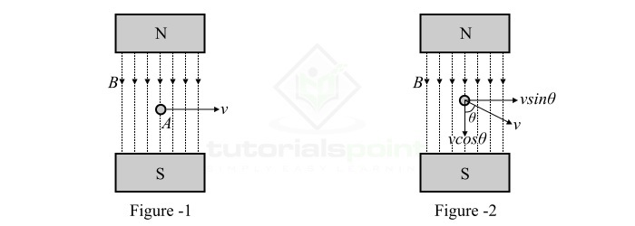
Consider a single conductor of length l meters located in a uniform magnetic field of magnetic flux density B Wb/m2 as shown in Figure-1. This conductor is moving at right angles relative to the magnetic field with a velocity of v m/s.
Now, if the conductor moves through a small distance dx in time dt seconds, then the area swept by the conductor is given by,
$$\mathrm{\mathit{A\:=\:l\times dx\:}\mathrm{m^{\mathrm{2}}}}$$
Therefore, the magnetic flux cut by the conductor is given by,
$$\mathrm{\mathit{d\phi }\:=\:\mathrm{Flux\:density\times Area\: swept}}$$
$$\mathrm{\Rightarrow \mathit{d\phi }\:=\:\mathit{B\times l\times dx}\:\mathrm{Wb}}$$
According to Faradays law of electromagnetic induction, the EMF induced in the conductor is given by,
$$\mathrm{\mathit{e}\:=\:\mathit{N}\frac{\mathit{d\phi }}{\mathit{dt}}\:=\:\mathit{N}\frac{\mathit{Bldx}}{\mathit{dt}}}$$
Since, we have taken only a single conductor, thus N = 1.
$$\mathrm{\mathit{e}\:=\:\mathit{Blv}\:\mathrm{volts}\cdot \cdot \cdot (1)}$$
Where, v = dx/dt, velocity of the conductor in the magnetic field.
If there is angular motion of the conductor in the magnetic field and the conductor moves at an angle relative to the magnetic field as shown in Figure-2. Then, the velocity at which the conductor moves across the magnetic field is equal to "vsinθ". Thus, the induced EMF is given by,
$$\mathrm{\mathit{e}\:=\:\mathit{B\:l\:v}\:\mathrm{sin\mathit{\theta }}\:\mathrm{volts}\cdot \cdot \cdot (2)}$$
Statically Induced EMF
When a stationary conductor is placed in a changing magnetic field, the induced EMF in the conductor is known as statically induced EMF. The statically induced EMF is further classified into following two types −
Self-Induced EMF
Mutually Induced EMF
Self Induced EMF
When EMF is induced in a conductor or coil due to change of its own magnetic flux linkage, it is known as self-induced EMF.
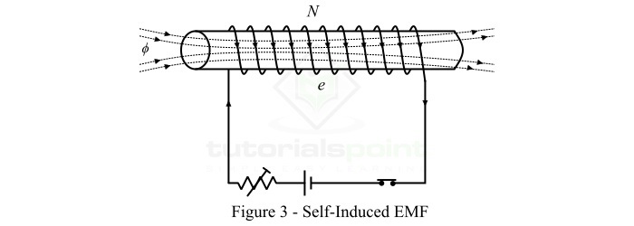
Consider a coil of N turn as shown in Figure-3. The current flowing through the coil establishes a magnetic field in the coil. If the current in the coil changes, then the magnetic flux linking the coil also changes. This changing magnetic field induces an EMF in the coil according to the Faradays law of electromagnetic induction. This EMF is known as self-induced EMF and the magnitude of the self-induced EMF is given by,
$$\mathrm{\mathit{e}\:=\:\mathit{N}\frac{\mathit{d\phi }}{\mathit{dt}}}$$
Mutually Induced EMF
The EMF induced in a coil due to the changing magnetic field of a neighboring coil is known as mutually induced EMF.
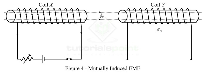
Consider two coils X and Y placed adjacent to each other as shown in Figure-4. Here, a fraction of the magnetic flux produced by the coil X links with the coil Y. This magnetic flux of coil X which is common to both coils X and Y is known as mutual flux ($\mathit{\phi _{m}}$).
If the current in coil X is changed, then the mutual flux also changes and hence EMF is induced in both the coils. Where, the EMF induced in coil X is known as self-induced EMF and the EMF induced in coil Y is called mutually induced EMF.
According to Faradays law, the magnitude of the mutually induced EMF is given by,
$$\mathrm{\mathit{e_{m}}\:=\:\mathit{N_{Y}}\frac{\mathit{d\phi _{m}}}{\mathit{dt}}}$$
Where,$\mathit{N_{Y}}$ is the number of turns in coil Y and $\frac{\mathit{d\phi _{m}}}{\mathit{dt}}$ is rate of change of mutual flux.
