- Electrical Machines - Home
- Basic Concepts
- Electromechanical Energy Conversion
- Energy Stored in Magnetic Field
- Singly-Excited and Doubly Excited Systems
- Rotating Electrical Machines
- Electrical Machines Types
- Faraday’s Laws of Electromagnetic Induction
- Concept of Induced EMF
- Fleming's Left Hand and Right Hand Rules
- Transformers
- Electrical Transformer
- Construction of Transformer
- EMF Equation of Transformer
- Turns Ratio and Voltage Transformation Ratio
- Ideal Transformer
- Practical Transformer
- Ideal and Practical Transformers
- Transformer on DC
- Losses in a Transformer
- Efficiency of Transformer
- 3-Phase Transformer
- Types of Transformers
- More on Transformers
- Transformer Working Principle
- Single-Phase Transformer Working Principle
- 3-Phase Transformer Principle
- 3-Phase Induction Motor Torque-Slip
- 3-Phase Induction Motor Torque-Speed
- 3-Phase Transformer Harmonics
- Double-Star Connection (3-6 Phase)
- Double-delta Connection (3-6 Phase)
- Transformer Ratios
- Voltage Regulation
- Delta-Star Connection (3-Phase)
- Star-Delta Connection (3-Phase)
- Autotransformer Conversion
- Back-to-back Test (Sumpner's Test)
- Transformer Voltage Drop
- Autotransformer Output
- Open and Short Circuit Test
- 3-Phase Autotransformer
- Star-Star Connection
- 6-Phase Diametrical Connections
- Circuit Test (Three-Winding)
- Potential Transformer
- Transformers Parallel Operation
- Open Delta (V-V) Connection
- Autotransformer
- Current Transformer
- No-Load Current Wave
- Transformer Inrush Current
- Transformer Vector Groups
- 3 to 12-Phase Transformers
- Scott-T Transformer Connection
- Transformer kVA Rating
- Three-Winding Transformer
- Delta-Delta Connection Transformer
- Transformer DC Supply Issue
- Equivalent Circuit Transformer
- Simplified Equivalent Circuit of Transformer
- Transformer No-Load Condition
- Transformer Load Condition
- OTI WTI Transformer
- CVT Transformer
- Isolation vs Regular Transformer
- Dry vs Oil-Filled
- DC Machines
- Construction of DC Machines
- Types of DC Machines
- Working Principle of DC Generator
- EMF Equation of DC Generator
- Derivation of EMF Equation DC Generator
- Types of DC Generators
- Working Principle of DC Motor
- Back EMF in DC Motor
- Types of DC Motors
- Losses in DC Machines
- Applications of DC Machines
- More on DC Machines
- DC Generator
- DC Generator Armature Reaction
- DC Generator Commutator Action
- Stepper vs DC Motors
- DC Shunt Generators Critical Resistance
- DC Machines Commutation
- DC Motor Characteristics
- Synchronous Generator Working Principle
- DC Generator Characteristics
- DC Generator Demagnetizing & Cross-Magnetizing
- DC Motor Voltage & Power Equations
- DC Generator Efficiency
- Electric Breaking of DC Motors
- DC Motor Efficiency
- Four Quadrant Operation of DC Motors
- Open Circuit Characteristics of DC Generators
- Voltage Build-Up in Self-Excited DC Generators
- Types of Armature Winding in DC Machines
- Torque in DC Motors
- Swinburne’s Test of DC Machine
- Speed Control of DC Shunt Motor
- Speed Control of DC Series Motor
- DC Motor of Speed Regulation
- Hopkinson's Test
- Permanent Magnet DC Motor
- Permanent Magnet Stepper Motor
- DC Servo Motor Theory
- DC Series vs Shunt Motor
- BLDC Motor vs PMSM Motor
- Induction Motors
- Introduction to Induction Motor
- Single-Phase Induction Motor
- 3-Phase Induction Motor
- Construction of 3-Phase Induction Motor
- 3-Phase Induction Motor on Load
- Characteristics of 3-Phase Induction Motor
- Speed Regulation and Speed Control
- Methods of Starting 3-Phase Induction Motors
- More on Induction Motors
- 3-Phase Induction Motor Working Principle
- 3-Phase Induction Motor Rotor Parameters
- Double Cage Induction Motor Equivalent Circuit
- Induction Motor Equivalent Circuit Models
- Slip Ring vs Squirrel Cage Induction Motors
- Single-Cage vs Double-Cage Induction Motor
- Induction Motor Equivalent Circuits
- Induction Motor Crawling & Cogging
- Induction Motor Blocked Rotor Test
- Induction Motor Circle Diagram
- 3-Phase Induction Motors Applications
- 3-Phase Induction Motors Torque Ratios
- Induction Motors Power Flow Diagram & Losses
- Determining Induction Motor Efficiency
- Induction Motor Speed Control by Pole-Amplitude Modulation
- Induction Motor Inverted or Rotor Fed
- High Torque Cage Motors
- Double-Cage Induction Motor Torque-Slip Characteristics
- 3-Phase Induction Motors Starting Torque
- 3-phase Induction Motor - Rotor Resistance Starter
- 3-phase Induction Motor Running Torque
- 3-Phase Induction Motor - Rotating Magnetic Field
- Isolated Induction Generator
- Capacitor-Start Induction Motor
- Capacitor-Start Capacitor-Run Induction Motor
- Winding EMFs in 3-Phase Induction Motors
- Split-Phase Induction Motor
- Shaded Pole Induction Motor
- Repulsion-Start Induction-Run Motor
- Repulsion Induction Motor
- PSC Induction Motor
- Single-Phase Induction Motor Performance Analysis
- Linear Induction Motor
- Single-Phase Induction Motor Testing
- 3-Phase Induction Motor Fault Types
- Synchronous Machines
- Introduction to 3-Phase Synchronous Machines
- Construction of Synchronous Machine
- Working of 3-Phase Alternator
- Armature Reaction in Synchronous Machines
- Output Power of 3-Phase Alternator
- Losses and Efficiency of an Alternator
- Losses and Efficiency of 3-Phase Alternator
- Working of 3-Phase Synchronous Motor
- Equivalent Circuit and Power Factor of Synchronous Motor
- Power Developed by Synchronous Motor
- More on Synchronous Machines
- AC Motor Types
- Induction Generator (Asynchronous Generator)
- Synchronous Speed Slip of 3-Phase Induction Motor
- Armature Reaction in Alternator at Leading Power Factor
- Armature Reaction in Alternator at Lagging Power Factor
- Stationary Armature vs Rotating Field Alternator Advantages
- Synchronous Impedance Method for Voltage Regulation
- Saturated & Unsaturated Synchronous Reactance
- Synchronous Reactance & Impedance
- Significance of Short Circuit Ratio in Alternator
- Hunting Effect Alternator
- Hydrogen Cooling in Synchronous Generators
- Excitation System of Synchronous Machine
- Equivalent Circuit Phasor Diagram of Synchronous Generator
- EMF Equation of Synchronous Generator
- Cooling Methods for Synchronous Generators
- Assumptions in Synchronous Impedance Method
- Armature Reaction at Unity Power Factor
- Voltage Regulation of Alternator
- Synchronous Generator with Infinite Bus Operation
- Zero Power Factor of Synchronous Generator
- Short Circuit Ratio Calculation of Synchronous Machines
- Speed-Frequency Relationship in Alternator
- Pitch Factor in Alternator
- Max Reactive Power in Synchronous Generators
- Power Flow Equations for Synchronous Generator
- Potier Triangle for Voltage Regulation in Alternators
- Parallel Operation of Alternators
- Load Sharing in Parallel Alternators
- Slip Test on Synchronous Machine
- Constant Flux Linkage Theorem
- Blondel's Two Reaction Theory
- Synchronous Machine Oscillations
- Ampere Turn Method for Voltage Regulation
- Salient Pole Synchronous Machine Theory
- Synchronization by Synchroscope
- Synchronization by Synchronizing Lamp Method
- Sudden Short Circuit in 3-Phase Alternator
- Short Circuit Transient in Synchronous Machines
- Power-Angle of Salient Pole Machines
- Prime-Mover Governor Characteristics
- Power Input of Synchronous Generator
- Power Output of Synchronous Generator
- Power Developed by Salient Pole Motor
- Phasor Diagrams of Cylindrical Rotor Moto
- Synchronous Motor Excitation Voltage Determination
- Hunting Synchronous Motor
- Self-Starting Synchronous Motor
- Unidirectional Torque Production in Synchronous Motor
- Effect of Load Change on Synchronous Motor
- Field Excitation Effect on Synchronous Motor
- Output Power of Synchronous Motor
- Input Power of Synchronous Motor
- V Curves & Inverted V Curves of Synchronous Motor
- Torque in Synchronous Motor
- Construction of 3-Phase Synchronous Motor
- Synchronous Motor
- Synchronous Condenser
- Power Flow in Synchronous Motor
- Types of Faults in Alternator
- Miscellaneous Topics
- Electrical Generator
- Determining Electric Motor Load
- Solid State Motor Starters
- Characteristics of Single-Phase Motor
- Types of AC Generators
- Three-Point Starter
- Four-Point Starter
- Ward Leonard Speed Control Method
- Pole Changing Method
- Stator Voltage Control Method
- DOL Starter
- Star-Delta Starter
- Hysteresis Motor
- 2-Phase & 3-Phase AC Servo Motors
- Repulsion Motor
- Reluctance Motor
- Stepper Motor
- PCB Motor
- Single-Stack Variable Reluctance Stepper Motor
- Schrage Motor
- Hybrid Schrage Motor
- Multi-Stack Variable Reluctance Stepper Motor
- Universal Motor
- Step Angle in Stepper Motor
- Stepper Motor Torque-Pulse Rate Characteristics
- Distribution Factor
- Electrical Machines Basic Terms
- Synchronizing Torque Coefficient
- Synchronizing Power Coefficient
- Metadyne
- Motor Soft Starter
- CVT vs PT
- Metering CT vs Protection CT
- Stator and Rotor in Electrical Machines
- Electric Motor Winding
- Electric Motor
- Useful Resources
- Quick Guide
- Resources
- Discussion
Types of Electrical Machines
An electrical machine is a device which either converts electrical energy into mechanical energy or mechanical energy into electrical energy. Depending on the type of supply used, connection of winding, or working principle, electrical machines can be classified into several different types such as AC machines, DC machines, induction motor, synchronous machine, and many others.
In this chapter, we will learn about these different types of electrical machines along with their features and applications.
Types of Electrical Machines
The following figure shows the types of electrical machines in different categories −
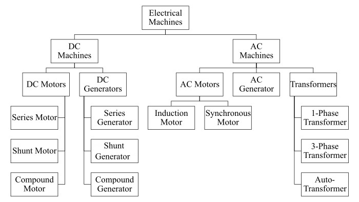
Lets discuss about each type of electrical machine in detail.
DC Machine
DC machine, also known as a direct current machine, is a type of electrical machine which takes direct current supply as input and converts it into rotational mechanical energy as output. Depending on the function it performs, DC machines are of two types namely,
- DC Motor − A DC motor is nothing but a DC machine which converts input direct current electricity into rotational mechanical energy. DC motors are further classified into three main types which are - DC series motor, DC shunt motor, and DC compound motor.
- DC Generator − A DC generator is a DC machine which converts input mechanical energy into direct current electricity as output. Similar to DC motor, DC generators are also classified into three key types namely, DC series generator, DC shunt generator, and DC compound generator.
Let's get an overview of different types of DC motors and generators.
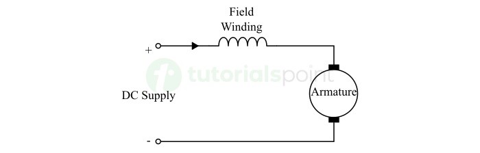
DC Series Motor
DC series motor is a type of self-excited DC motor in which the field winding is connected in series with the armature winding. Hence, in a DC series motor, the armature winding and field winding carry the same electric current. The connection diagram of a DC series motor is shown in the following figure.
The following are some key features of the DC series motor −
- DC series motor has a very high starting torque.
- The speed of a DC series motor decreases with the increasing load. Hence, it has a poor speed regulation.
- Due to series connection of field and armature windings, a DC series motor draws a high electric current.
- DC series motors have simple design and require less maintenance.
- DC series motors are relatively economical.
DC series motors are mainly used in applications that require high starting torque, such as −
- Electric cars or scooters
- Cranes and hoists
- Electric locomotives
- Grinders, etc.
DC Shunt Motor
DC shunt motor is another type of self-excited DC motor in which the field winding is connected in parallel with the armature winding. Thus, in a DC shunt motor, the armature winding and field winding carry different electric currents depending upon their winding resistances. The connection diagram of a DC shunt motor is shown in the following figure.

The key features of DC shunt motors are highlighted below −
- DC shunt motors operate at a constant speed.
- DC shunt motors provide a moderate starting torque.
- DC shunt motors have a relatively simple speed control mechanism.
- DC shunt motors are self-regulating.
Due to constant speed and moderate starting torque, the following are some common applications of dc shunt motors −
- Lathes and milling machines
- Wood working machines
- Washing machines
- Metal cutting machines
- Small printing presses
- Elevators, etc.
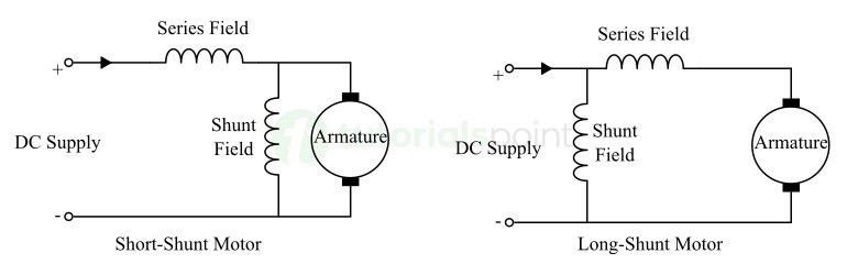
DC Compound Motor
A DC compound motor is a special type of DC motor which has both series and shunt field windings. Hence, this type of dc motor combines the features of both series and shunt motors and provides a proper combination of high starting torque and speed regulation.
DC compound motors have two different types of connections namely,
- Long shunt − In this connection, the shunt winding is connected in parallel with the series combination of armature and series field windings.
- Short shunt − In this connection, the series winding is connected in series with the parallel combination of the armature and shunt field windings.
The circuit diagrams of the long shunt dc compound motor and short shunt dc compound motor are shown in the following figure.
The following are some key features of DC compound motors −
- DC compound motors have a high starting torque.
- DC compound motor provides efficient speed regulation.
- DC compound motor combines the characteristics of series and shunt motors.
DC compound motors are widely used in a verity of applications including the following −
- Industrial machinery
- Power and machine tools
- Shears
- Presses
- Reciprocating machines, etc.
This is all about different types of dc motors, let's now learn about different types of dc generators.
DC Series Generator
A dc series generator is a type of dc generator in which the field winding is connected in series with the armature winding, as shown in the following circuit diagram.
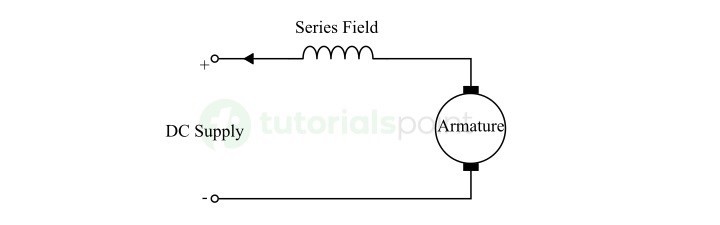
In a dc series generator, the same current flows through the armature winding, field winding, and the load.
Some main features of the dc series generator are listed below −
- The terminal voltage increases with the increase in load current.
- Beyond a certain limit of load current, the terminal voltage drops with the increasing load current.
- DC series generator has a rising voltage characteristic.
DC series generators are mainly used in the following applications −
- Used in DC locomotives to supply field excitation current for regenerative breaking.
- Used as a booster in distribution feeders to compensate voltage drop.
- Also used in series arc lightening, etc.
DC Shunt Generator
A DC shunt generator is a type of dc generator in which the field winding is connected in parallel with the armature winding. Thus, in this generator, the armature current supplies both the field current and the load current.
The circuit diagram of a dc shunt generator is depicted in the following figure.

The key features of the dc shunt generator are given below −
- DC shunt generator provides a constant voltage output across a wide range of load currents.
- DC shunt generator has a good voltage regulation.
- DC shunt generator requires a low current for field excitation during startup.
- The terminal voltage of a dc shunt generator slightly decreases due to internal drops and armature reaction.
DC shunt generators are widely employed in applications that require a constant voltage supply, such as −
- Battery chargers
- General lighting schemes
- Powering up electronic devices and systems, etc.
DC Compound Generator
A DC compound generator is a type of dc generator which has two sets of the field winding namely, series field winding and shunt field winding. Depending on the connection arrangement, there are two types of dc compound generators namely, long-shunt dc compound generator and short-shunt dc compound generator. Both these connection arrangements are shown in the following figure.
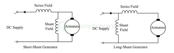
DC compound generators are mainly used in the following key applications −;
- DC compound generators are used for supplying power for lighting and heavy power services.
- DC compound generators are also used for driving electric motors.
- DC compound generators are also used in hotels, offices, and other building types for power supply.
- DC compound generators having differential compounding effect are used in arc welding.
AC Machines
AC machines are those electrical machines that convert either alternating current electricity into mechanical energy or mechanical energy into alternating current electricity. These electrical machines have their armature winding always located on the stator and the field winding located on the rotor.
Depending on the function, AC machines can be classified into two types namely AC Motors and AC Generators. Let's discuss about different types of AC machines in detail.
AC Motor
An AC motor is an electrical machine that converts alternating current electricity into rotational mechanical energy. AC motors are broadly classified into two main types namely, induction motors and synchronous motors. Which are explain below in more detail.
AC Generator
An AC generator is an electrical machine which converts rotational mechanical energy into alternating current electricity. Since it generates alternating current electricity, it is also known as alternator. AC generator is also referred to as synchronous generator.
Transformer
An electrical transformer is an electrical machine which has no moving components and used for changing or transforming the levels of voltage or current without changing the frequency and power at the input and output. Electrical transformer is a special machine, as it does not perform electromechanical energy conversion.
Induction Motor
An induction motor is a type of AC electric motor which converts alternating current electricity into mechanical energy by using the principle of electromagnetic induction. This type of AC motor runs at a speed slower than the synchronous speed, hence it is also known as asynchronous motor.

Depending on the power supply used, induction motors are of two types namely, single-phase induction motor and three-phase induction motor. Single-phase motors are used to drive small loads like fans, coolers, air-conditioners, washing machines, etc. while three-phase induction motors are used for operating heavy load like industrial machinery.
The following are some key characteristics of induction motors −
- Induction motors always operate at a speed slightly less than the synchronous speed.
- Induction motors are self-starting.
- Induction motors are highly reliable and simpler in construction.
Synchronous Motor
A synchronous motor is a type of AC electric motor which operates at a constant speed, called synchronous speed. The speed of rotation of the motor shaft is synchronized with the frequency of the electric supply. A typical synchronous motor has two magnetic fields, one is stator magnetic field and another is rotor magnetic field. Hence, a synchronous motor is a doubly-excited machine.

Small synchronous motors are mainly used in timing applications like synchronous clock or timers used in various appliances. While large sized synchronous motors are used in industrial applications like power factor improvement, driving rolling or ball mills, etc.
Some of the key features of synchronous motors are highlighted below −
- Synchronous motors operate at a constant speed.
- Synchronous motors cannot be self-starting.
- Synchronous motors require an additional excitation for rotor circuit.
- Synchronous motors provide facilities to control the power factor of supply.
AC Generator
AC Generator, also known as Alternator or Synchronous Generator, is a type of electric generator that produces alternating current electricity. Hence, we can define it as an electromechanical device that converts mechanical energy into alternating current electricity.
AC generators can be broadly classified into two types namely, single-phase AC generator and three-phase AC generator. A single-phase AC generator is one that produces single-phase electricity and mostly used in domestic and commercial applications, while a three-phase AC generator produces three-phase electricity and mainly used in industrial and large-scale applications.
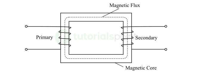
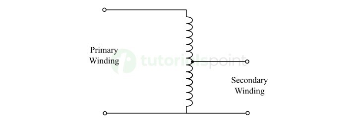
Single-Phase Transformer
A single-phase transformer is an electrical transformer which has only one pair of primary and secondary windings. It is used in distribution systems and small-scale applications for voltage and current transformation. It has three main components namely, a primary winding, a secondary winding, and a laminated magnetic core as shown in the figure below.
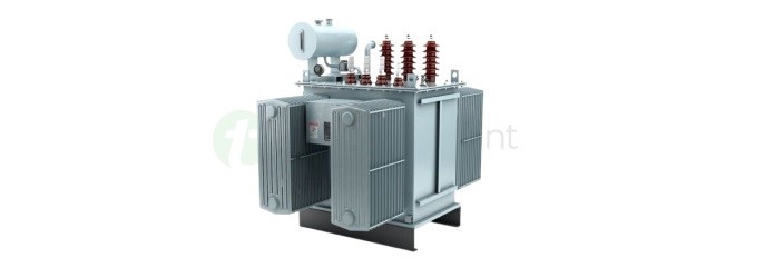
Three-Phase Transformer
A three-phase transformer is a large-sized electrical transformer which consists of three pairs of primary and secondary windings, one for each phase. These three-phase windings are connected in either star or delta connection. Three-phase transformers are mainly used in power transmission and distribution systems for regulating the supply voltage and current.
Autotransformer
An autotransformer is a special type of electrical transformer which has only one winding, acting as both primary and secondary.
In this transformer, the input voltage is applied across two terminals of the primary winding and the output voltage is taken across two terminals of the secondary winding, where terminal is common between the primary and secondary.
Autotransformer transfers electricity from one circuit to another through conduction and induction, because it has only one coil. It is widely used in motor starters, transmission lines and distribution feeders to compensate voltage drops, in testing benches, etc.
Conclusion
In this chapter, we presented an overview of various types of electrical machines along with their circuit diagrams and key features. Here, we touched upon the fundamental concepts of both AC and DC electrical machines, including DC motors, DC generators, AC motors, AC generators, and transformers.
