- Electrical Machines - Home
- Basic Concepts
- Electromechanical Energy Conversion
- Energy Stored in Magnetic Field
- Singly-Excited and Doubly Excited Systems
- Rotating Electrical Machines
- Electrical Machines Types
- Faraday’s Laws of Electromagnetic Induction
- Concept of Induced EMF
- Fleming's Left Hand and Right Hand Rules
- Transformers
- Electrical Transformer
- Construction of Transformer
- EMF Equation of Transformer
- Turns Ratio and Voltage Transformation Ratio
- Ideal Transformer
- Practical Transformer
- Ideal and Practical Transformers
- Transformer on DC
- Losses in a Transformer
- Efficiency of Transformer
- 3-Phase Transformer
- Types of Transformers
- More on Transformers
- Transformer Working Principle
- Single-Phase Transformer Working Principle
- 3-Phase Transformer Principle
- 3-Phase Induction Motor Torque-Slip
- 3-Phase Induction Motor Torque-Speed
- 3-Phase Transformer Harmonics
- Double-Star Connection (3-6 Phase)
- Double-delta Connection (3-6 Phase)
- Transformer Ratios
- Voltage Regulation
- Delta-Star Connection (3-Phase)
- Star-Delta Connection (3-Phase)
- Autotransformer Conversion
- Back-to-back Test (Sumpner's Test)
- Transformer Voltage Drop
- Autotransformer Output
- Open and Short Circuit Test
- 3-Phase Autotransformer
- Star-Star Connection
- 6-Phase Diametrical Connections
- Circuit Test (Three-Winding)
- Potential Transformer
- Transformers Parallel Operation
- Open Delta (V-V) Connection
- Autotransformer
- Current Transformer
- No-Load Current Wave
- Transformer Inrush Current
- Transformer Vector Groups
- 3 to 12-Phase Transformers
- Scott-T Transformer Connection
- Transformer kVA Rating
- Three-Winding Transformer
- Delta-Delta Connection Transformer
- Transformer DC Supply Issue
- Equivalent Circuit Transformer
- Simplified Equivalent Circuit of Transformer
- Transformer No-Load Condition
- Transformer Load Condition
- OTI WTI Transformer
- CVT Transformer
- Isolation vs Regular Transformer
- Dry vs Oil-Filled
- DC Machines
- Construction of DC Machines
- Types of DC Machines
- Working Principle of DC Generator
- EMF Equation of DC Generator
- Derivation of EMF Equation DC Generator
- Types of DC Generators
- Working Principle of DC Motor
- Back EMF in DC Motor
- Types of DC Motors
- Losses in DC Machines
- Applications of DC Machines
- More on DC Machines
- DC Generator
- DC Generator Armature Reaction
- DC Generator Commutator Action
- Stepper vs DC Motors
- DC Shunt Generators Critical Resistance
- DC Machines Commutation
- DC Motor Characteristics
- Synchronous Generator Working Principle
- DC Generator Characteristics
- DC Generator Demagnetizing & Cross-Magnetizing
- DC Motor Voltage & Power Equations
- DC Generator Efficiency
- Electric Breaking of DC Motors
- DC Motor Efficiency
- Four Quadrant Operation of DC Motors
- Open Circuit Characteristics of DC Generators
- Voltage Build-Up in Self-Excited DC Generators
- Types of Armature Winding in DC Machines
- Torque in DC Motors
- Swinburne’s Test of DC Machine
- Speed Control of DC Shunt Motor
- Speed Control of DC Series Motor
- DC Motor of Speed Regulation
- Hopkinson's Test
- Permanent Magnet DC Motor
- Permanent Magnet Stepper Motor
- DC Servo Motor Theory
- DC Series vs Shunt Motor
- BLDC Motor vs PMSM Motor
- Induction Motors
- Introduction to Induction Motor
- Single-Phase Induction Motor
- 3-Phase Induction Motor
- Construction of 3-Phase Induction Motor
- 3-Phase Induction Motor on Load
- Characteristics of 3-Phase Induction Motor
- Speed Regulation and Speed Control
- Methods of Starting 3-Phase Induction Motors
- More on Induction Motors
- 3-Phase Induction Motor Working Principle
- 3-Phase Induction Motor Rotor Parameters
- Double Cage Induction Motor Equivalent Circuit
- Induction Motor Equivalent Circuit Models
- Slip Ring vs Squirrel Cage Induction Motors
- Single-Cage vs Double-Cage Induction Motor
- Induction Motor Equivalent Circuits
- Induction Motor Crawling & Cogging
- Induction Motor Blocked Rotor Test
- Induction Motor Circle Diagram
- 3-Phase Induction Motors Applications
- 3-Phase Induction Motors Torque Ratios
- Induction Motors Power Flow Diagram & Losses
- Determining Induction Motor Efficiency
- Induction Motor Speed Control by Pole-Amplitude Modulation
- Induction Motor Inverted or Rotor Fed
- High Torque Cage Motors
- Double-Cage Induction Motor Torque-Slip Characteristics
- 3-Phase Induction Motors Starting Torque
- 3-phase Induction Motor - Rotor Resistance Starter
- 3-phase Induction Motor Running Torque
- 3-Phase Induction Motor - Rotating Magnetic Field
- Isolated Induction Generator
- Capacitor-Start Induction Motor
- Capacitor-Start Capacitor-Run Induction Motor
- Winding EMFs in 3-Phase Induction Motors
- Split-Phase Induction Motor
- Shaded Pole Induction Motor
- Repulsion-Start Induction-Run Motor
- Repulsion Induction Motor
- PSC Induction Motor
- Single-Phase Induction Motor Performance Analysis
- Linear Induction Motor
- Single-Phase Induction Motor Testing
- 3-Phase Induction Motor Fault Types
- Synchronous Machines
- Introduction to 3-Phase Synchronous Machines
- Construction of Synchronous Machine
- Working of 3-Phase Alternator
- Armature Reaction in Synchronous Machines
- Output Power of 3-Phase Alternator
- Losses and Efficiency of an Alternator
- Losses and Efficiency of 3-Phase Alternator
- Working of 3-Phase Synchronous Motor
- Equivalent Circuit and Power Factor of Synchronous Motor
- Power Developed by Synchronous Motor
- More on Synchronous Machines
- AC Motor Types
- Induction Generator (Asynchronous Generator)
- Synchronous Speed Slip of 3-Phase Induction Motor
- Armature Reaction in Alternator at Leading Power Factor
- Armature Reaction in Alternator at Lagging Power Factor
- Stationary Armature vs Rotating Field Alternator Advantages
- Synchronous Impedance Method for Voltage Regulation
- Saturated & Unsaturated Synchronous Reactance
- Synchronous Reactance & Impedance
- Significance of Short Circuit Ratio in Alternator
- Hunting Effect Alternator
- Hydrogen Cooling in Synchronous Generators
- Excitation System of Synchronous Machine
- Equivalent Circuit Phasor Diagram of Synchronous Generator
- EMF Equation of Synchronous Generator
- Cooling Methods for Synchronous Generators
- Assumptions in Synchronous Impedance Method
- Armature Reaction at Unity Power Factor
- Voltage Regulation of Alternator
- Synchronous Generator with Infinite Bus Operation
- Zero Power Factor of Synchronous Generator
- Short Circuit Ratio Calculation of Synchronous Machines
- Speed-Frequency Relationship in Alternator
- Pitch Factor in Alternator
- Max Reactive Power in Synchronous Generators
- Power Flow Equations for Synchronous Generator
- Potier Triangle for Voltage Regulation in Alternators
- Parallel Operation of Alternators
- Load Sharing in Parallel Alternators
- Slip Test on Synchronous Machine
- Constant Flux Linkage Theorem
- Blondel's Two Reaction Theory
- Synchronous Machine Oscillations
- Ampere Turn Method for Voltage Regulation
- Salient Pole Synchronous Machine Theory
- Synchronization by Synchroscope
- Synchronization by Synchronizing Lamp Method
- Sudden Short Circuit in 3-Phase Alternator
- Short Circuit Transient in Synchronous Machines
- Power-Angle of Salient Pole Machines
- Prime-Mover Governor Characteristics
- Power Input of Synchronous Generator
- Power Output of Synchronous Generator
- Power Developed by Salient Pole Motor
- Phasor Diagrams of Cylindrical Rotor Moto
- Synchronous Motor Excitation Voltage Determination
- Hunting Synchronous Motor
- Self-Starting Synchronous Motor
- Unidirectional Torque Production in Synchronous Motor
- Effect of Load Change on Synchronous Motor
- Field Excitation Effect on Synchronous Motor
- Output Power of Synchronous Motor
- Input Power of Synchronous Motor
- V Curves & Inverted V Curves of Synchronous Motor
- Torque in Synchronous Motor
- Construction of 3-Phase Synchronous Motor
- Synchronous Motor
- Synchronous Condenser
- Power Flow in Synchronous Motor
- Types of Faults in Alternator
- Miscellaneous Topics
- Electrical Generator
- Determining Electric Motor Load
- Solid State Motor Starters
- Characteristics of Single-Phase Motor
- Types of AC Generators
- Three-Point Starter
- Four-Point Starter
- Ward Leonard Speed Control Method
- Pole Changing Method
- Stator Voltage Control Method
- DOL Starter
- Star-Delta Starter
- Hysteresis Motor
- 2-Phase & 3-Phase AC Servo Motors
- Repulsion Motor
- Reluctance Motor
- Stepper Motor
- PCB Motor
- Single-Stack Variable Reluctance Stepper Motor
- Schrage Motor
- Hybrid Schrage Motor
- Multi-Stack Variable Reluctance Stepper Motor
- Universal Motor
- Step Angle in Stepper Motor
- Stepper Motor Torque-Pulse Rate Characteristics
- Distribution Factor
- Electrical Machines Basic Terms
- Synchronizing Torque Coefficient
- Synchronizing Power Coefficient
- Metadyne
- Motor Soft Starter
- CVT vs PT
- Metering CT vs Protection CT
- Stator and Rotor in Electrical Machines
- Electric Motor Winding
- Electric Motor
- Useful Resources
- Quick Guide
- Resources
- Discussion
Practical Transformer on Load
When a load Impedance is connected across the secondary winding of the practical transformer, then the transformer is said to be loaded and draws a load which flows through the secondary winding and the load.
We shall consider following two cases for analysing the practical transformer −
Case 1 - When the Transformer is Assumed to have no Winding Resistance and Leakage Flux
The figure shows a practical transformer with the assumption that the winding resistances and the leakage reactances are neglected. With this assumption,
$$\mathrm{V_{1} \: = \: E_{1} \: and \: V_{2} \: = \: E_{2}}$$

Consider an inductive load is connected across the secondary winding which causes the secondary current I2 to lag the secondary voltage V2 by an angle 2. In this case, the total primary current I1 must fulfil two requirements −
- First, it must supply the no-load current I0 to produce the iron losses and the magnetic flux in core of the transformer.
- Secondly, it must supply a current I’2 to neutralise the demagnetising effect of secondary current I2.
The magnitude of current I’2 is given by,
$$\mathrm{N_{1}I'_{2} \: = \: N_{2}I_{2}}$$
$$\mathrm{\Rightarrow \: I'_{2} \: = \: \frac{N_{2}}{N_{1}}I_{2} \: = \: KI_{2}}$$
Therefore, the total primary current drawn by a practical transformer under loaded condition is given the phasor sum of I’2 and I0 i.e.
$$\mathrm{I_{1} \: = \: I'_{2} \: + \: I_{0}}$$
Where,
$$\mathrm{I'_{2} \: = \: - KI_{2}}$$
The negative sign shows that the current I'2 is 180° out of phase with current I2.

The phasor diagram shows that both the emfs E1 and E2 lag behind the mutual flux (m) by 90°. The current I'2 denotes the portion of primary current which neutralise the demagnetising effect of the secondary current (I2). Therefore, the current I'2 must be in anti-phase with I2. The phasor I0 represents the no-load current of the transformer. The phasor sum of I’2 and I0 represents the total primary current (I1). Hence,
$$\mathrm{\text{primary power factor } \: = \: \cos \varphi_{1}}$$
$$\mathrm{\text{Secondary power factor } \: = \: \cos \varphi_{2}}$$
Therefore,
$$\mathrm{\text{Input power, } \: P_{1} \: = \: V_{1}I_{1} \: \cos \varphi_{1}}$$
$$\mathrm{\text{Output power, } \: P_{2} \: = \: V_{2}I_{2} \: \cos \varphi_{2}}$$
Case 2 - When the Transformer has Winding Resistance and Leakage Flux
The figure shows a practical transformer having winding resistances and leakage reactances. This is the actual case that exits in a practical transformer. Here, some of the applied voltage is dropped in the primary winding resistance R1 and leakage reactance X1, thus the primary EMF (E1) will be less than the applied voltage V1.
similarly, there being a voltage drop in the secondary winding resistance R2 and the leakage reactance X2 so that the voltage across the secondary winding terminals V2 will be less than the secondary EMF (E2).

Now, consider an inductive load connected across the secondary winding of the transformer which causes the secondary current I2 to lag behind the secondary voltage V2 by an angle 2 and the total primary current (I1) must fulfil two requirements −
- First, it must supply the no-load current I0 to produce the iron losses and the magnetic flux in core of the transformer.
- Secondly, it must supply a current I'2 to neutralise the demagnetising effect of secondary current I2.
The magnitude of current I'2 is given by,
$$\mathrm{N_{1}I'_{2} \: = \: N_{2}I_{2}}$$
$$\mathrm{\Rightarrow \: I'_{2} \: = \: \frac{N_{2}}{N_{1}}I_{2} \: = \: KI_{2}}$$
Therefore, the total primary current drawn by a practical transformer under loaded condition is given the phasor sum of I'2 and I0 i.e.
$$\mathrm{I_{1} \: = \: I'_{2} \: + \: I_{0}}$$
Where,
$$\mathrm{I'_{2} \: = \: - KI_{2}}$$
The negative sign shows that the current I'2 is 180° out of phase with current I2.
Now, by applying KVL in primary loop and secondary loop, we get the applied primary voltage (V1) and secondary terminal voltage (V2) as,
$$\mathrm{V_{1} \: = \: - E_{1} \: + \: I_{1}(R_{1} \: + \: jX_{1})}$$
$$\mathrm{\Rightarrow \: V_{1} \: = \: - E_{1} \: + \: I_{1}Z_{1}}$$
And,
$$\mathrm{V_{2} \: = \: E_{2} \: - \: I_{2}(R_{2} \: + \: jX_{2})}$$
$$\mathrm{\Rightarrow \: V_{2} \: = \: E_{2} \: - \: I_{2}Z_{2}}$$
The bold letters shows the phasor sum.
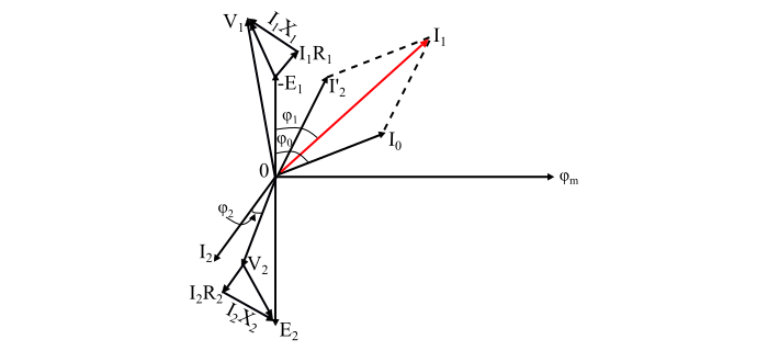
From the phasor diagram, it can be seen that both the EMFs E1 and E2 lag behind the mutual flux (m) by 90°. The current I'2 represents the primary current to counteract the demagnetising effect of secondary current (I2) which in anti-phase with I2. The current I0 is the no-load current of the transformer. Thus, the total primary current (I1) is obtained by the phasor sum of I'2 and I0.
Also, the primary voltage (V1) is obtained by adding (phasor sum) the drop I1R1 and I1X1 to the counter EMF (- E1). The secondary terminal voltage V2 is obtained by subtracting (phasor difference) I2R2 and I2X2 from EMF (E2).
The input and output power factors are given by,
$$\mathrm{\text{Input power factor } \: = \: \cos \varphi_1}$$
$$\mathrm{\text{Output power factor } \: = \: \cos \varphi_2}$$
Also, the input and output powers of the transformer is given by,
$$\mathrm{\text{Input power, } \: P1 \: = \: V_{1}I_{1} \: \cos \varphi_1}$$
$$\mathrm{\text{Output power, } \: P2 \: = \: V_{2}I_{2} \: \cos \varphi_2}$$
Numerical Example
A 440/120 V single phase transformer takes no-load current of 6 A at 0.3 lagging power factor. If the secondary winding supplies a current of 100 A at a power factor 0.85 lagging. Determine the current taken by the primary winding.
Solution
Here, the primary current I1 is given by phasor sum of I'2 and I0, thus,
$$\mathrm{\cos\varphi_{0} \: = \: 0.3; \:\: \therefore \:\: \varphi_{0} \: = \: 72.54^{\circ}}$$
$$\mathrm{\cos\varphi_{2} \: = \: 0.85; \:\: \therefore \:\: \varphi_{2} \: = \: 31.79^{\circ}}$$
Now, the transformation ratio is,
$$\mathrm{K \: = \: \frac{V_{2}}{V_{1}} \: = \: \frac{120}{440} \: = \: \frac{3}{11}}$$
Therefore,
$$\mathrm{I'_{2} \: = \: KI_{2} \: = \: \left(\frac{3}{11}\right) \: \times \: 100 \: = \: 27.27 A}$$

Refer the phasor diagram, the angle between I'2 and I0 is
$$\mathrm{\theta \: = \: 72.54 \: - \: 31.79 \: = \: 40.75^{\circ}}$$
Now, using the parallelogram law of vector addition, the primary current is
$$\mathrm{I_{1} \: = \: \sqrt{(I'_{2})^2 \: + \: (I_{0})^2 \: + \: 2I_{0}I'_{2}\: \cos \theta}}$$
$$\mathrm{\Rightarrow \: I_{1} \: = \: \sqrt{(27.27)^2 \: + \: (6)^2 \: + \: (2 \: \times \: 6 \: \times \: 27.27 \: \times \: \cos 40.75)} \: = \: 32.05 \: A}$$