 Data Structure
 Networking
 RDBMS
RDBMS Operating System
 Java
Java MS Excel
 iOS
iOS HTML
HTML CSS
CSS Android
 Python
 C Programming
 C++
C++ C#
C# MongoDB
 MySQL
MySQL Javascript
 PHP
PHP
- Selected Reading
- UPSC IAS Exams Notes
- Developer's Best Practices
- Questions and Answers
- Effective Resume Writing
- HR Interview Questions
- Computer Glossary
- Who is Who
Operational modes of 8255
There are three modes of operation which are supported by 8255. We call them as mode 0, mode1 and mode 2.
We call the mode 0 as the simple Input Output or the basic Input Output for performing the simplest mode of operation. Every ports of 8255 can be programmed to work in mode 0.
We call mode 1 as the strobed Input Output or handshake Input Output. It is useful when data is supplied to the input device by the microprocessor at irregular interval of time. Finally, when the data is read by the processor the port informs the Input device that the processors already read the data. This information is provided by signals which are called as handshake signals. These handshake signals are provided by port C. Only port A and B works in mode 1. Then 5 lines of Port C uses mode 0. In mode 0 and 1 a port works as an Input port or Output port. It is dependent if the Input device or Output device gets connected to the port. It is useful for the microprocessor to receive information and sometimes sends information to the Input Output device which is connected to the port.
Mode2 is called as bidirectional handshake Input Output. An example to be cited as floppy disc controller card. Moreover, in mode 0 or 1 a port works as an input or output port.
Hence it can be concluded that −
Port A works in mode 0, mode 1, or mode 2 respectively;
Port B can only work in mode 0 or mode 1;
Port C works in mode 0 if and only if Port A and Port B are in mode 0. Else, any free lines of Port C, after the allocation of handshake lines, are used in mode 0.
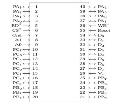
The pin diagram of 8255 is shown below:

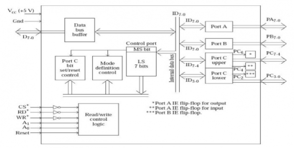
We address Port C Upper and Port C lower such that they constitute a port of 8 bit uniquely. Hence we divide port C into 2 parts having 4 bits. Hence we program Port C lower as Input and Port C upper as Output.

The following table depicts the how the port selection is being done in 8255.
| A1 | A0 | Port Selected |
|---|---|---|
| 0 | 0 | Port A |
| 0 | 1 | Port B |
| 1 | 0 | Port C |
| 1 | 1 | Control Port |

