
Article Categories
- All Categories
-
 Data Structure
-
 Networking
-
 RDBMS
RDBMS
-
 Operating System
-
 Java
Java
-
 MS Excel
-
 iOS
iOS
-
 HTML
HTML
-
 CSS
CSS
-
 Android
-
 Python
-
 C Programming
-
 C++
C++
-
 C#
C#
-
 MongoDB
-
 MySQL
MySQL
-
 Javascript
-
 PHP
PHP
-
 Economics & Finance
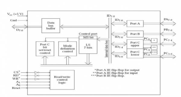
Control port of 8255
In 8255, there are two types of command words or control word are available. And they are −
Mode definition control word and
Port C bit set/reset control word.
Both these are written to the control port only. From the point of view of the microprocessor there is a single 8-bit control port, which is selected when CS* = 0, WR* = 0, A1 = 1 and A0 = 1. But if we consider the architecture of 8255, internally there are two control ports, one for mode definition control and another for Port C bit set/reset control. The contents of the control port get latched in mode definition control port if the MS bit of control port = 1. If the MS bit of control port = 0, the contents of the control port gets latched in Port C bit set/reset control port. This can be seen from the following fig.
Now let us discuss about the Mode Definition Control Word. The following fig depicts the same −
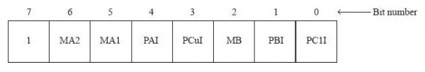
The following table depicts the meaning and purposes for all these bits −
| Bit 0 (PClI) | 1 = Port C lower (PC3-0) as input 0 = Port C lower (PC3-0) as output |
| Bit 1 (PBI) | 1 Port B as input 0 = Port B as output |
| Bit 2 (MB) | 1 = Port B in mode 1 0 = Port B in mode 0 |
| Bit 3 (PCuI) | 1 = Port C upper (PC7-4) as input 0 = Port C upper (PC7-4) as output |
| Bit 4 (PAI) | 1 = Port A as input 0 = Port A as output |
| Bits 6, 5 | 0 0 = Port A in mode 0 |
| (MA2,MA1) | 0 1 = Port A in mode 1 1 0 = Port A in mode 2 1 1 = Port A in mode 2 |
| Bit 7 | Must be 1 to indicate that it is mode definition control. |
Now let us discuss about the Port C Bit Set/Reset C4 Word. The following fig depicts the same −
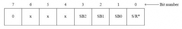
The following table depicts the meaning and purposes for all these bits −
| Bit 0 (S/R*) | 1 = Set Port C bit selected by bits 3, 2, and 1 0 = Reset Port C bit selected by bits 3, 2, and 1 |
| Bits 3, 2, 1 (SB2, 1, 0) | 000 = Select bit 0 of Port C 001 = Select bit 1 of Port C 010 = Select bit 2 of Port C 011 = Select bit 3 of Port C 100 = Select bit 4 of Port C 101 = Select bit 5 of Port C 110 = Select bit 6 of Port C 111 = Select bit 7 of Port C |
| Bits 6, 5, 4 | Are don't cares. Generally loaded with 000 |
| Bit 7 | 0 to indicate it is Port C bit set/reset control |

6K+ Views
