
Article Categories
- All Categories
-
 Data Structure
-
 Networking
-
 RDBMS
RDBMS
-
 Operating System
-
 Java
Java
-
 MS Excel
-
 iOS
iOS
-
 HTML
HTML
-
 CSS
CSS
-
 Android
-
 Python
-
 C Programming
-
 C++
C++
-
 C#
C#
-
 MongoDB
-
 MySQL
MySQL
-
 Javascript
-
 PHP
PHP
-
 Economics & Finance
Addressing modes of 6800
We have seen the Internal structure and registers of Motorola M6800 Microprocessor. In this section we will see the addressing modes of M6800.
There are six addressing modes in M6800 MPU. These modes are −
- Immediate Addressing Mode
- Implied Addressing Mode
- Direct Addressing Mode
- Extended Addressing Mode
- Indexed Addressing Mode
- Relative Addressing Mode
Now Let us see some basic syntax of M6800 Assembly Language Programming.
If a number is 8CH in hexadecimal, then we have to use $ sign before it. So it will be $8C. A number without $ is treated as decimal number. Similarly, an immediate data is denoted by # symbol. #50FF is a data, but without #, it is memory location.
In 8085 or Z-80, for an instruction the two operands in an instruction is like (destination, source). But in this case, it is inverse, so at first the source address will be given. (Source, Destination).
For 16-bit data or address, in 8085 or Z-80 the first Byte was the Least Significant Byte. But for M6800, the first Byte is Most Significant Byte. As an example, if the instruction is STA A $AFC4, then the hex code will be B7 AF C4.
Now let us see the addressing modes of the Motorola M6800.
Immediate Addressing
In this Immediate Addressing Mode, the data is provided in the instruction itself. The data is provided immediately after the opcode.
LDA B, #$26 In this instruction the hexadecimal data 26 is loaded to the Accumulator B. So here the data is provided directly after the opcode.
Implied Addressing
This Implied Addressing mode is also known as Inherent Addressing Mode. In this mode, the operands are not in the memory. So for an example, we can say that CLC. This instruction is used to clear the carry flag, and set it to 0. So it does not take any operand. Similarly, ASL B instruction performs the arithmetic left shift of B. So here also the operand is not in the memory.
Direct Addressing
In the direct addressing mode, the operands are located in memory. In this case the address space is 00H to FFH so it is also called the page 0 addressing mode. The instruction SUB B, $FE is used to subtract the content of location FEH from B and store it into B. The direct addressing mode takes two Bytes of memory space. So it takes less time to execute.
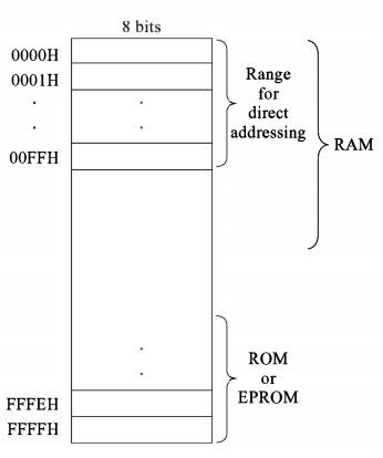
In M6800 the frequently accessed data stored in the memory range 0000H to 00FFH. So for fast accessing the data from these locations, RAM generally starts from 0000H. And using ROM or EPROM provides the last part of memory, which is ending with FFFFH.
Extending Addressing
In 8085, there was Absolute Addressing Mode, which is similar to the Extending addressing mode of M6800. So we have to provide 16-bit address after the opcode to get the data from any location in the memory.
The instruction NEG $FE00, it will negate the content of the location FE00H
Indexed Addressing
In this indexed addressing mode, the operand is stored into the memory. A part of memory is provided by the index register (IX). Another 8-bit part is provided in the instruction. After adding that data with the index register content, the instruction can get the effective address to access the memory location.
So if the Index Register content is A5CEH, the instruction ADC B $10, X will add the content of register B and A5DEH with carry.
Relative Addressing
Relative addressing is done for the branching instructions. These instructions are two-Byte long. It takes signed 8-bit number. So after executing correct instruction it jumps to backward or forward using this signed data.
As an example, there is an instruction like BEQ $F0. So it means when the zero flag is enabled, it jumps 10H location backward (As the 2’s complement of -10H is F0H) from the next instruction location.

2K+ Views
