
Article Categories
- All Categories
-
 Data Structure
-
 Networking
-
 RDBMS
RDBMS
-
 Operating System
-
 Java
Java
-
 MS Excel
-
 iOS
iOS
-
 HTML
HTML
-
 CSS
CSS
-
 Android
-
 Python
-
 C Programming
-
 C++
C++
-
 C#
C#
-
 MongoDB
-
 MySQL
MySQL
-
 Javascript
-
 PHP
PHP
-
 Economics & Finance
Implementation of SOP Function using Multiplexer
An Overview
Implementing logical functions is a basic part of designing digital logic. The sum-of-products (SOP) form, which defines a logical function as the sum of various product terms, is one common representation. Data selectors, commonly referred to as multiplexers, are adaptable combinational circuits that can be used to effectively implement SOP functions. In this article, we'll examine how to create SOP functions using multiplexers and go over the specific steps involved.
SOP Function
A Boolean expression known as a sum-of-products (SOP) function represents a logical function as the addition (OR) of many product terms. The literals in each product word are either variables or their opposites. The canonical form or the minterm form are other names for the SOP form.
Here is an illustration of a SOP function with three A, B, and C input variables
F(A, B, C) = ?(0, 2, 5, 6)
Four product terms?m0, m2, m5, and m6?are represented by the logical OR of the function F in this instance. Each minterm (m) represents a particular set of values for the input variables where the function evaluates to 1.
The example's minterms are represented in binary as follows
m0 000 (corresponds to the decimal value 0)
m2 010 (corresponds to the decimal value 2)
m5 101 (corresponds to the decimal value 5)
m6 110 (corresponds to the decimal value 6)
Logic gates or a multiplexer can be used to accomplish the SOP function.
Multiplexer
A combinational logic circuit called a multiplexer, also referred to as a data selector, chooses one of several input data lines and routes it to a single output line dependent on the control inputs. It is frequently shown as a block diagram with a single output, data inputs, and control inputs.
A multiplexer is typically represented by the following symbol
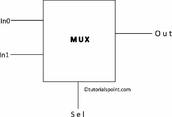
The data inputs are denoted by letters A0 to A3, the control inputs are denoted by letters S0 and S1, and the output is denoted by the letter O. The type of multiplexer determines the number of data inputs and control inputs.
Which data input is chosen and transmitted to the output is determined by the control inputs. The output matches the chosen data input, while the control inputs are typically in binary format.
Consider a 4-to-1 multiplexer as an illustration, which has a single output (O), two control inputs (S0 and S1), and four data inputs (A0 to A3). The following is the multiplexer's truth table
S1 |
S0 |
A3 |
A2 |
A1 |
A0 |
O |
|---|---|---|---|---|---|---|
0 |
0 |
D3 |
D2 |
D1 |
D0 |
D0 |
0 |
1 |
D3 |
D2 |
D1 |
D0 |
D1 |
1 |
0 |
D3 |
D2 |
D1 |
D0 |
D2 |
1 |
1 |
D3 |
D2 |
D1 |
D0 |
D3 |
The appropriate data input is chosen and directed to the output based on the control inputs S1 and S0. For instance, the output O will be equal to the data input D1 if S1=0 and S0=1.
Implementation of SOP Function Using Multiplexer
Now let's look at how to create a SOP function using a multiplexer step by step
Count the Input Variables The first step is to count the input variables for the SOP function. Let's use "n" to represent this number.
Determine the Multiplexer Configuration the multiplexer configuration to be determined: Determine how many control inputs the multiplexer needs. The formula c = log2(n), rounding up the amount if necessary, can be used to determine the quantity of control inputs, indicated as "c."
Calculate the Data Inputs The total number of SOP terms in your function equals the number of data inputs for the multiplexer.
Control Inputs to SOP Terms to Assign Each SOP word should be associated with a particular set of control inputs. Represent the inputs to the controls using binary values. For instance, with two control inputs (c = 2), there are four combinations that are possible: 00, 01, 10, and 11.
Assign Data Inputs for Each SOP Term Give the multiplexer's data input lines the corresponding binary value for each SOP word. If the SOP term contains an input variable, assign '1' to the data input line; if the input variable is negated, assign '0'.
Connect Control Inputs Join the multiplexer's control inputs to the SOP function's equivalent inputs.
Connect Output Connect the multiplexer's output to the SOP function's desired output.
Repeat Steps for Each SOP Term For each SOP term in your function, repeat steps 4 through 7, assigning control inputs and data inputs and linking them appropriately.
Implementation Steps
The following steps are necessary to implement the SOP function using a multiplexer
Create the truth tables for the functions with the specified amount of variables first.
One variable is regarded as the input, while the other variables are thought of as line selectors.
The input variable and its complement are then considered rows in the resulting matrix, with the input lines of the MUX acting as columns.
Discover the AND then between the rows.
Everything discovered is regarded as the input.
For example
Given SOP function f(A, B, C) = m(0, 1, 4, 6, 7) and MUX is
Consequently, a 4X1 MUX and inverter were needed for the logical function to be implemented.
Let A and B are the select lines and C be the input, four data input lines of 4X1 multiplexer are labeled as a,b,c,d respectively. C? is the inverted input of C, C can be either 0 or 1.
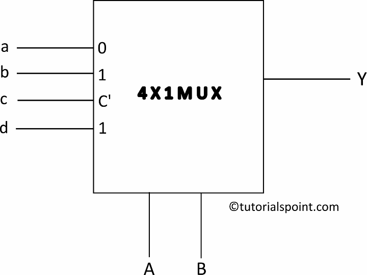
f(A,B,C ) Y = m(0, 1, 4, 6, 7), if ( a = 1 , b = 0, c = C?, d = 1)
Below K Map represents that to get the final output as m(0, 1, 4, 6, 7) i.e respective values are highlighted as yellow in below table, the input data provided on input lines should be ( a = 1 , b = 0, c = C?, d = 1 ) respectively.
a |
b |
c |
d |
|
|---|---|---|---|---|
C? |
0 |
2 |
4 |
6 |
C |
1 |
3 |
5 |
7 |
1 |
0 |
C? |
1 |
Logical functions can be realized more quickly by employing multiplexers to implement SOP functions. Designers can effectively create SOP functions with fewer components, less complexity, and increased circuit efficiency by following the step-by-step procedure described in this article. Multiplexers are essential components of digital logic architecture and are a great option for implementing SOP functions and other logical operations in a variety of applications due to their versatility.

6K+ Views
