- DirectX - Home
- 3D MATHS
- 3D Maths - Vector Algebra
- 3D Maths - Matrix Algebra
- 3D Maths - Transformations
- 3D Maths - DirectX Math
- DIRECTX
- DirectX - Overview
- DirectX - Installation
- DirectX - Components
- DirectX - Tools
- DirectX - Creating App
- DirectX - Window Events
- DirectX - App Lifecycle
- DirectX - Direct3D Initialization
- DirectX - First HLSL
- DirectX - Graphics Pipeline
- DirectX - Buffers
- DirectX - 3D Transformation
- DirectX - Drawing
- DirectX - Rendering
- DirectX - Modeling
- DirectX - Lighting
- DirectX - Texturing
- DirectX - Multi Texturing
- DirectX - Blending
- DirectX - Picking
- DirectX - Stenciling
- DirectX - First Shader
- DirectX - Pixel Shader
- DirectX - Geometry Shaders
- DirectX - Compute Shaders
- DirectX - Shader Effects
- DirectX - Quaternion
- DirectX Resources
- DirectX - Quick Guide
- DirectX - Useful Resources
- DirectX - Discussion
DirectX - Quick Guide
3D Maths - Vector Algebra
The 3D mathematical model always refers to vectors as their basic points. In geometry and 3D mathematical model, a point is a location in space. A point does not have any predefined size, the only unique property it includes is location. With respect to computer graphics, a point is usually considered as a vertex of 3D figure.
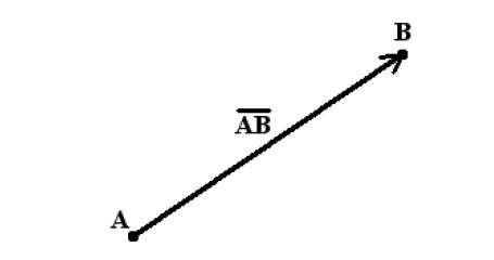
The following figure refers to the schematic representation of vector −
A point indirectly defines a vector. A geometrical vector includes two major properties which are mentioned below −
- Length
- Direction
Length defines the distance between start and end point. Direction includes the path where a vector defines its initial and end point. The vector will never include a fixed location in space. If this happens, then it is considered as a line segment. This property makes 3D computer graphics easy to understand and interpret.
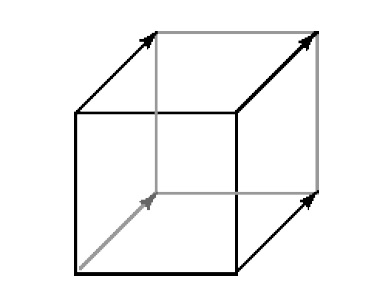
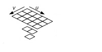
This combination of "distance and direction" for a vector is referred as a displacement. Most often the same displacement is applied to each of several points in 3D view. The best illustration for this is a cube. The front face includes four vertices which can be referred as four points. If a user tries to move the same distance and direction from each of these points for a specified cube, it is observed that you reach the four vertices of the back face.
The "same distance and direction" is a vector, shown in the figure above as a line with an arrow head. The snapshot shows the representation of one vector four times, once for each point of the face. Now let us focus on various terminologies of a vector.
Definition of Vector
A vector can be defined as an object which includes both magnitude and direction. The schematic representation of a vector can be considered as a directed line segment. It includes length in magnitude and with an arrow indicating the direction. Certain terminologies are equally important for a vector which are mentioned below −
Initial Point − For a vector AB, A is referred as an initial point.
Terminal Point − For a vector AB, B is referred as an terminal point.
Magnitude − The total length between initial point and terminal point of a vector i.e., from A to B is referred as the magnitude or length of the vector AB.
Now let us focus on various types of vectors which will be beneficial for our tutorial point of view.
Types of Vectors
The following are the types of Vectors −
Zero Vector/Null Vector − A vector whose initial and terminal points coincide as a single point is referred as zero vector.
Unit Vector − A vector whose length is unity, i.e., 1 is said to be unit vector. The representation is a so that | a | = 1.
Collinear Vectors − The vectors which are parallel to the same line, are considered to be collinear vectors.
Co-initial Vectors − Two or more vectors having the same initial point are called co-initial vectors.
Negative of a vector − A vector whose length is same as that of a given vector AB, but the only difference is with respect to direction, is known as negative of vector AB. The representation is mentioned below −
BA = AB
Equal Vectors − If two vectors ar and br have the same length and direction without any dependency of the positions of their initial points, such vectors are said to be equal. It is represented below −
a r = b r
3D Maths - Matrix Algebra
Sometimes, there arises a question with developers what if we are interested only in direction, not location or length. The scenario results in usage of only direction which results in vector formation.
A vector may be represented with list of elements in vertical and horizontal format called column matrix or row matrix. In a column matrix, an ordered list of numbers is written in a column, whereas in row matrix the elements are written in row format.
The dimension of matrix is defined with number of rows and columns combined together. The representation of matrix is mentioned below −
$$\begin{bmatrix}\:\:\:2\:.\:9 \\-4\:.\:6 \\\:\:\:0\:.\:0 \end{bmatrix}$$The numbers represented in matrix in row or column format is called as an element. The numbers are actually real numbers. The number of elements defined in matrix as a vector is called as dimension.
A row matrix is defined as an ordered list of numbers written in a row. Here is the demonstration of a row matrix which is mentioned below −
$$(12.5,\:-9.34)$$Vectors in 3D algebra is always represented with column matrices. Now let us demonstrate that with the following example −
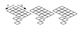
$$Column\:Matrix\begin{bmatrix}\:\:\:2\:.\:9 \\-4\:.\:6 \\\:\:\:0\:.\:0 \end{bmatrix}\begin{bmatrix}-13.45 \\\:92.4\\\:\:\:2.0\\-42.01 \end{bmatrix}\begin{bmatrix}2\\0\\5\\1 \end{bmatrix}$$The dimension of first matrix is 3*2, the second matrix is 4*1 and third matrix is also same with a value of 4.
The elements of a column matrix can be variables. The following schematic representation shows variable matrix −
$$\begin{bmatrix}u\\v\\w\end{bmatrix}\begin{bmatrix}x_0\\x_1\\x_2\end{bmatrix}\begin{bmatrix}z_1\\z_2\\z_3\end{bmatrix}$$The first element in a column matrix is usually represented with index 0 and sometimes 1.
Type of Matrices
The following are the types of matrices −
Row Matrix
A row matrix is a matrix which defines only one row. Its order can be considered as 1 X C, where C is the number of columns. The demonstration of row matrix is mentioned below with a dimension of 1 X 5 −
$$[3\:5\:7\:9\:11]$$Column Matrix
A column matrix is a matrix with a dimension of only one column. It is represented by an order of R X 1, where R is represented with number of rows. The demonstration of column matrix of the order 3 X 1 −
$$\begin{bmatrix}2\\5\\7 \end{bmatrix}\\$$Square Matrix
The square matrix is the number of rows which is equal to the number of columns is referred as a square matrix. Here's a square matrix of the order 2 X 2 −
$$\begin{bmatrix}4\:\:\:9\\15\:\:\:2\\ \end{bmatrix}$$Diagonal Matrix
A diagonal matrix is defined as a square matrix where all the elements are 0 except for those in the diagonal from the top left corner to the bottom right corner. The demonstration of diagonal matrix of order 4 X 4 −
$$\begin{bmatrix}8\:\:0\:\:0\:\:0\\0\:\:5\:\:0\:\:0\\ 0\:\:0\:\:2\:\:0\\ 0\:\:0\:\:0\:\:9\end{bmatrix}$$3D Maths - Transformations
In this chapter, we will focus more on 3D rotations or transformations. 3D rotation is not considered as same as 2D rotation. In 3D rotation or transformations, it is important that we specify the angle of rotation along with the axis of rotation. The user can perform 3D rotation about X, Y, and Z axes. The matrix representation with all axes is mentioned below −
$$\begin{bmatrix}x' \\y'\\z' \end{bmatrix}=\begin{bmatrix}1 & 0 & 0\\ 0 & cos(\theta) & -sin(\theta)\\ 0 &sin(\theta) &cos(\theta) \end{bmatrix}\begin{bmatrix}x \\y\\z \end{bmatrix}Rotation\:around\:x\:axis$$ $$\begin{bmatrix}x' \\y'\\z' \end{bmatrix}=\begin{bmatrix}cos(\theta)& 0 &-sin(\theta) \\ 0 & 1& 0 \\ sin (\theta)& 0 &cos(\theta) \end{bmatrix}\begin{bmatrix}x \\y\\z \end{bmatrix}Rotation\:around\:y\:axis$$ $$\begin{bmatrix}x' \\y'\\z' \end{bmatrix}=\begin{bmatrix}cos(\theta) &-sin(\theta)& 0 \\ sin(\theta) & cos(\theta)& 0 \\ 0& 0 &1 \end{bmatrix}\begin{bmatrix}x \\y\\z \end{bmatrix}Rotation\:around\:z\:axis$$There are various types of transformations which take place in 3D Algebra as follows −
- Linear Transformation
- Affine Transformation
Now it is important to focus on each one of them to understand the mathematical theory underneath.
Linear Transformation
A linear transformation usually consists of input and output values which is completely different from 3D vectors.
Consider the following example which describes linear transformation for representation of matrix. The mathematical function which we will interpret is as follows −
T (v) = T(x , y , z) = (x, y, z).
This function takes input as 3D vector and gives an output of a 3D vector. With this equation, it is clearly visible that includes a constant value linear transformation if and only if following conditions are true −
T (u + v) = T (u) + T (v)
T (k u) = kT (u)
where u = (ux ,uy ,uz) and v = (vx ,vy ,vz) are any 3D vectors, and k is a scalar.
Affine Transformation
If the value of constant b is considered 0, the affine transformation reduces to a linear transformation. This means the user can represent any linear transformation by a 4 4 affine matrix. For example, the scaling and rotation matrices written using 4 4 matrices is described in demonstration below −
$$S= \begin{bmatrix}s_x&0 &0 &0 \\ 0 &s_y &0 &0 \\0 &0 &s_z &0 \\0 &0 &0 &1 \\\end{bmatrix}$$ $$R_n=\begin{bmatrix} c+(1-c)x^2&(1-c)xy+sz &(1-c)xz-sy &0 \\(1-c)xy-sz&c+(1-c)y^2 &(1-c)yz+sx &0 \\(1-c)xz+sy&(1-c)yz-sx &c+(1-c)z^2 &0 \\0&0 &0 &1 \\\end{bmatrix}$$In this way, we can express all of our transformations consistently using 4 4 matrices and points and vectors using 1 4 homogeneous row vectors.
3D Maths - DirectX Math
The initialization process of Direct3D requires some specific Direct3D types and basic graphics concepts. This chapter addresses these requirements.
Direct3D includes a design of low-level graphics API (Application Programming Interface) that enables us to render 3D worlds using 3D hardware acceleration. The most important thing is that Direct3D provides the software interfaces through which a user can use the graphics hardware. The best illustration is to instruct the graphics hardware to clear the render target.
Now, let us focus on DirectXMath which is the primary focus of this chapter. DirectXMath is written with the help of standard Intel-style intrinsics, which is usually portable to all compilers. The ARM code paths use ARM-style intrinsics which is considered to be portable.
The DirectXMath library makes use of two commonly implemented extensions to Standard C++ which are mentioned below −
Anonymous structs, which are widely supported and are part of the C11 standard.
Anonymous unions, but these are part of the C++ and C99 standard.
DirectXMath is an inline SIMD which includes all the linear algebra library features for use in games and graphics apps.
The DirectXMath library includes inline features and uses only the concerned Visual C++ intrinsics. Hence, it is considered to be more compatible with all versions of Windows supported by Visual C++. There's no standard configuration which will put DirectXMath in the include path but a user can add it manually or make use of the NuGet package which is designed for that unique purpose. Keep in mind there are many differences which are completed with DirectX development for Windows XP support.
Migrating code
The details on moving from XNAMath to DirectXMath are covered in Code Migration from the XNA Math Library.
Make sure as a user you read all the details on the calling convention types which are designed to deal with the various architectures and vector calling conventions.
If a user is writing client code that is intended to build with both DirectXMath 3.06+ (Windows 8.1 SDK / VS 2013) and DirectXMath 3.03 (Windows 8 XDK / VS 2012), the following adapter code can be used −
#include <DirectXMath.h>
namespace DirectX {
   #if (DIRECTX_MATH_VERSION < 305) && !defined(XM_CALLCONV)
   #define XM_CALLCONV __fastcall
   typedef const XMVECTOR& HXMVECTOR;
   typedef const XMMATRIX& FXMMATRIX;
   #endif
}
DirectXMath includes all the written intrinsic standards, which should be portable to other compilers. The ARM codepaths also include ARM-style intrinsics which should be considered portable.
DirectX - Overview
Microsoft DirectX graphics include a set of APIs that help a user to create games and high-performance multimedia applications. The graphics of DirectX include support for high-performance 2D and 3D graphics.
For 3D graphics, it is always recommended to use Microsoft Direct3D 11 API. Even if a user has Microsoft Direct3D 9-level or Microsoft Direct3D 10-level hardware, the developer can implement Direct3D 11 API and target a feature level 9_x or feature level 10_x device.
DirectWrite and DirectComposition
For 2D graphics and text, it is recommended to use Direct2D and DirectWrite rather than Windows Graphics Device Interface (GDI).
The composition of bitmaps include Direct3D 11 or Direct2D populated, which uses DirectComposition.

Purpose
Direct2D is a hardware-accelerated, immediate-mode, 2D graphics API that includes high performance and high-quality rendering for 2D geometry, bitmaps, and text. The Direct2D API is designed for a user to interoperate well with GDI, GDI+, and Direct3D.
It is important to understand the target audience of Direct2D and 3D. It is designed primarily for use by the following classes of developers −
Developers who involve in large, enterprise-scale, native applications.
Developers who are involved in control toolkits and libraries for consumption by downstream developers.
Developers who are involved in server-side rendering of 2D graphics.
Developers who are known to use Direct3D graphics and need simple, high-performance 2D and text rendering for menus, user-interface (UI) elements, and Heads-up Displays (HUDs).
System Requirements
The system requirements are as follows −
Windows 8 or higher versions of Windows.
Windows Server 2008 R2 or Windows Server 2008 with Service Pack 2 (SP2) and Platform Update for Windows Server 2008 and later.
Direct3D on the other hand is a low-level API that can be used to draw triangles, lines, or points per frame.
The properties of Direct3D are mentioned below −
Hides different GPU implementations behind a coherent abstraction.
Designed to drive a separate graphics-specific processor.
Newer GPUs have hundreds or thousands of parallel processors.
Emphasizes parallel processing. A user can set up a bunch of rendering or compute state and then start an operation.
The official website of DirectX is −
www.microsoft.com/en-in/download/
From the mentioned link, it is clearly visible that it is a Microsoft product.
DirectX - Installation
As discussed in the previous chapter, DirectX is a Microsoft product and involves an executable which needs to be downloaded. Installation of DirectX requires a list of steps as mentioned below −
Step 1
Refer to the following website to download the product.
www.microsoft.com/en-in/download/

Step 2
Check the pre-requisites and download the executable file which is a must for DirectX software.
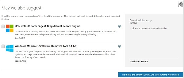
Step 3
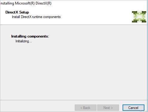
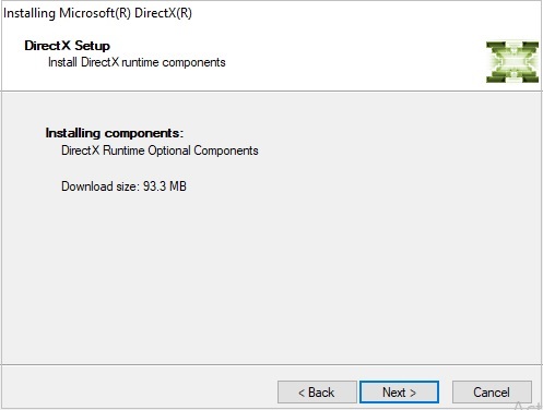
Check out the instructions in DirectX wizard which include all the details of runtime components. We need to accept the agreement to proceed with further installation process.
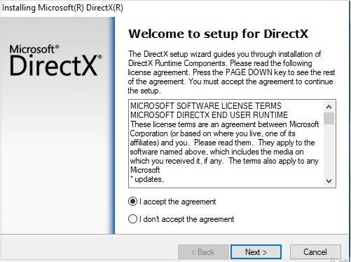
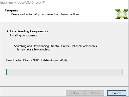
Step 4
You can observe the installation procedure steps as mentioned in snapshots.
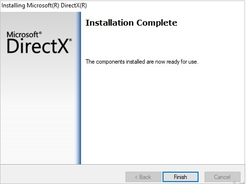
Step 5
This is considered as the final step when the installation is complete and successful.
DirectX - Components
DirectX is the Microsoft collection of APIs which is designed primarily to give game developers a low-level interface to the mentioned computer hardware which is running with Windows Operating System. Currently with version 12.0, each DirectX API component provides access to different aspects of the hardware, including graphics, sound, and networking, all through a standard interface. This interface allows programmers to include their games using one set of functions which is independent on the hardware used.
This chapter will focus more on the components of DirectX.
Components
The DirectX API includes multiple components, each of them representing a different aspect of the system. Each application programming interface can be used independently, thereby adding only the functionality that your game requires.
Below are the components of DirectX −
Graphics
This component manages all the graphics output. This API includes functions for handling all 2D and 3D graphics drawing, as well as initialization and setting the resolution for your game.
DirectInput
It includes management of all user input through this API. This component includes support for devices such as keyboard, mouse, gamepad, and joysticks.
It includes a new support feature for force-feedback.
DirectPlay
DirectPlay includes support for the user games through its API construct. These networking functions include communication with other machines allowing more than one person to play with them. DirectPlay includes a high-level interface for networking making users to implement every aspect of network communication.
DirectSound
DirectSound is a special API which is implemented when a user needs to add sound effects or background music. It includes a functionality to allow loading and playing one or more WAV files with a complete control access.
DirectMusic
This component allows user to create a dynamic soundtrack. Sounds can be played on the specified time schedule or adapted to the gameplay using the specific pitch, tempo, or volume changes.
DirectShow
This component allows streaming components with respect to soundtrack. It includes files in various formats such as AVI, MP3, MPEG and ASF files. With the help of DirectShow, there is no need to load entire file into memory, user can stream the file directly from CD.
DirectSetup
DirectSetup gives user the functionality to install the latest version of DirectX on the users computer.
DirectX - Tools
This chapter will focus on various tools which are being used for graphics. Basically, it comprises tools and utilities which are needed for DirectX.
A list of primary tools which are used in DirectX is mentioned below −
- Debugging DirectX apps
- Effect-Compiler Tool
- DxDiag ("DirectX Diagnostic Tool")
Debugging DirectX apps
We need editor to use debugging app. The user can use Visual Studio and the Windows 8 SDK to debug DirectX apps remotely. The Windows 8 SDK includes a set of components that support DirectX development and provide error checking with parameter. These components are .dll files like D3D11_1SDKLayers.dll, D2D1Debug1.dll, and Dxgidebug.dll.
Effect-Compiler Tool
FXC (fxc.exe) is an executable offline tool for compiling HLSL shaders for all the respective versions of Direct3D. The tool is located in the below link −
(SDK root)\Utilities\Bin\x86\
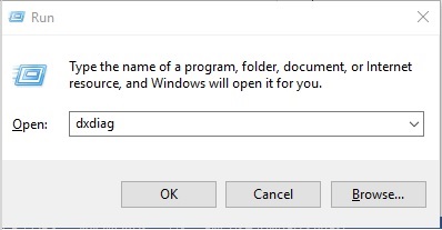
DxDiag ("DirectX Diagnostic Tool ")
DirectX includes a secret tool that is designed to troubleshoot problems basically for users who want to debug and analyze each and every step. The tool is called DirectX which helps us in identifying problems that are related to audio, display, video and any other multimedia applications with required features running on our computer.
This tool includes a special feature to find problems that occur with audio and video players of Windows 10 Operating system.
You can access this tool using Run prompt of Windows operating system as mentioned below −
In this chapter, we will be focusing on the usage of DirectX Diagnostic tool with respect to multimedia and graphics.
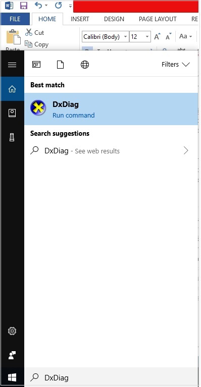
A simple search about the DirectX Diagnostic tool in Google search engine in case your personal computer is connected to the Internet will define the result as mentioned below −
Microsoft DirectX is a collection of Application Programming Interfaces (APIs) for handling tasks related to multimedia, especially game programming and video on Microsoft platforms.
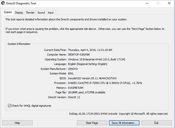
Once we look for this tool in our system, we get information divided into following sections −
System Information
The system information is shown in the below screenshot −
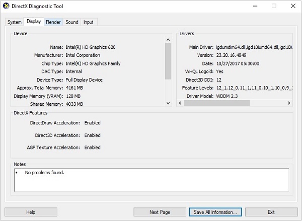
Display Information
The display information can be seen in the below screenshot −
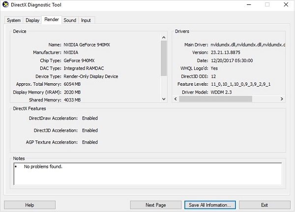
Render Data
The below screenshot shows the Render Data in the DirectX Diagnostic Tool −
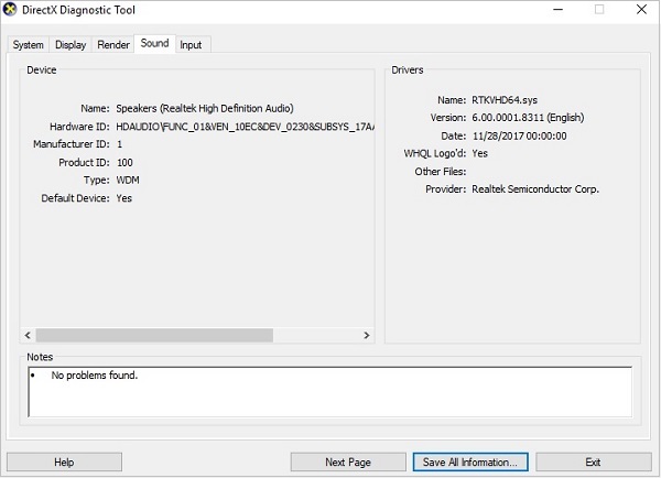
Sound Details
The sound details are shown in the below screenshot −
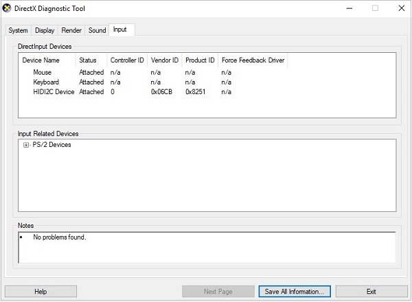
Input Details
The input details are shown in the below screenshot −
DirectX - Creating App
This chapter involves the process of creating new application with DirectX using Visual Studio Code Editor. Following steps should be followed for creating an app in DirectX −
Here we will start by constructing a DirectX project with a walk through of the basic steps to get a working application.
Step 1
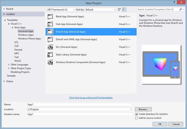
To create a DirectX non-desktop application, a special type of project called a DirectX App is used. This step involves opening a Visual Studio 2013, select File → New Project and select as DirectX App which comes under category of Visual C++, Store App, Universal App.
Step 2
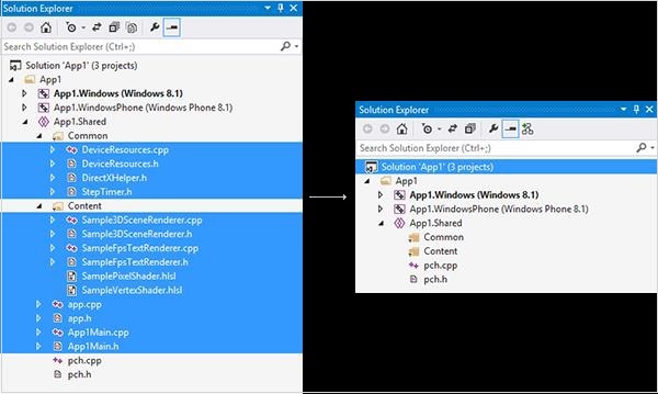
Once the project is created, you will see a lot of files being populated. This is clearly visible in snapshot mentioned below −
Step 3
User can delete various files to make up a sample app and explore the features to see how a fully-functioning DirectX app is set up as per the attributes required.
As mentioned in the snapshot above, a file is created named App.cpp.
#include <stdio.h> // include the standard input/output header file
int main(void) { // our program starts here
   printf("Hello World!"); // print "Hello World!" into the console
   return 0; // return 0 to windows
}
Explanation
The function main() marks the start of the application and works with Windows Operating System.
main() function should be included where the program usually starts.
Windows can feed the required parameters to get things done smoothly.
There are specific parameters which can be included usually considered as secondary parameters.
DirectX - Window Events
This chapter will focus on the events used in DirectX. It includes various user actions which can be detected by Windows. Whenever a particular event occurs, a notification is sent which describes about the event.
The life cycle of processing the events is mentioned below −
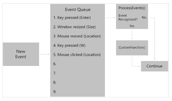
Whenever a new event is created, it is kept in queue. The events are listed priority-wise in the mentioned queue. ProcessEvents() is the function which will verify if the event is recognized or not. If yes it will move to CustomFunction() which focuses on further steps.
Handling events focuses on three basic parts −
- Instructing the window to dispatch the respective events
- Writing the functions to get the desired events
- Giving information to Windows about the list of functions
Now let us focus on each one and understand its importance.
Instruction to dispatch all events
Dispatching events is considered to be very simple. It is done with ProcessEvents() function. The code snippet for understanding this function is mentioned below −
virtual void Run() {
   // Obtain a pointer to the window
   CoreWindow^ Window = CoreWindow::GetForCurrentThread();

   // Run ProcessEvents() to dispatch events
   Window->Dispatcher->ProcessEvents(CoreProcessEventsOption::ProcessUntilQuit);
}
Run() refers to the initialization of event. GetForCurrentThread() is used to get a pointer to the window. Once the pointer is defined, it is considered to be the member of CoreWindow class. It automatically helps in processing events which is highlighted in the code snippet mentioned above.
Functions for the desired events
DirectX includes lots of events that can occur; but in this section, we will be interested only in specific events.
There is a special event called PointerPressed. It triggers when the user either clicks the mouse or when the touchscreen is touched with a pen or a finger. The event function need two major parameters as defined below −
void PointerPressed(CoreWindow^ Window , PointerEventArgs^ Args) {
}
The first parameter is CoreWindow which allows us to access information about the window. The second parameter is considered to be secondary and mentions about the pointer-press such as what type of press should be created i.e., mouse, pen and touch.
Information to Windows about the list of functions
In this section, we will focus on setting the parameters to give information to Windows about the list of functions.
Consider the code snippet mentioned below −
virtual void SetWindow(CoreWindow^ Window) {
   Window->PointerPressed += ref new TypedEventHandler
   <CoreWindow^, PointerEventArgs^>(this, &App::PointerPressed);
}
The CoreWindow parameter calls for PointerPressed which refers to the TypeEventHandler, thus specifying information to Windows with the list of functions.
DirectX - App Lifecycle
In this chapter, we will focus on various states of execution which is important from application point of view. A basic application includes three states of execution as given below −
- Running
- Suspended
- NotRunning
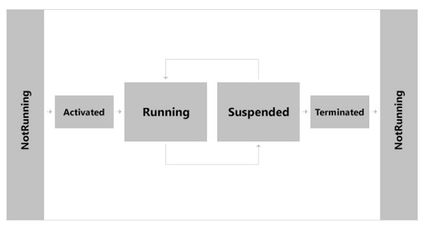
NotRunning
The application always starts with NotRunning state. Whenever the user is ready to play the game, user will activate it.
Activated
Whenever the game is initialized, it moves to the activated state. After the game is activated, the game moves to running state.
Running
In this state, the game is considered to be in Running state where all the required events are running.
Suspended
Whenever user is running the game, it may happen that user will leave the game or switches into some other app. This state is defined as Suspended state and it consumes very little battery.
Terminate
Windows may at any time decide the game to be closed to make it available for other apps. The user may sometimes close the app permanently. At this point, the game is Terminated and is returned to NotRunning state.
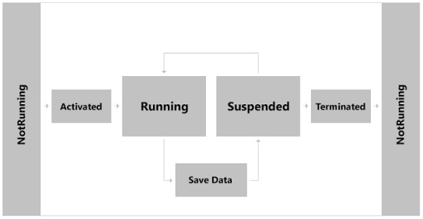
There is no explicit functionality to save the game, all you need to know is understanding the process lifecycle. Windows gives you a feature of five seconds duration before suspension and after running state to save any information which user wants to store before the game is fully suspended.
DirectX - Direct3D Initialization
The initialization process of Direct3D needs to be familiar with some basic Direct3D types and graphics concepts. In this chapter, we will focus on necessary steps to initialize Direct3D.
It includes a small detour which is taken to introduce accurate timing and the required time measurements needed for real-time graphics applications.
Now let us focus on Direct3D initialization process which requires us to be familiar with certain basic graphics concepts and Direct3D types.
Overview of Direct3D
It can be described as low-level graphics API (Application programming Interface) which enables us to render 3D worlds with the help of hardware acceleration. Direct3D includes various software interfaces through which a user can control the graphics hardware.
The best illustration is to instruct the graphics hardware to clear the mentioned target with the help of Direct3D method.
The main method is given below −
ID3D11DeviceContext::ClearRenderTargetView
The Direct3D layer is defined between the application and the graphics hardware, which means there is no need for a user to worry about the specifics of the 3D hardware as long as there is capability of Direct3D 11 capable device.
A Direct3D 11 capable graphics device must support the entire Direct3D 11 capability set, with few exceptions (i.e., the multisampling count still need to be queried, as they can vary between Direct3D 11 hardware). This is in contrast to Direct3D 9, where a device only had to support a subset of Direct3D 9 capabilities. Consequently, if a Direct3D 9 application wants to use a certain feature, it is necessary to first check if the available hardware supports that feature; as calling a Direct3D function not implemented by the hardware results in failure.
In Direct3D 11, device capability checking is no longer necessary because it is now a strict requirement that a Direct3D 11 device implement the entire Direct3D 11 capability set.
COM
Component Object Model (COM) is the technology that allows DirectX to be programming language independent and have backwards compatibility. Usually a user refers COM object as an interface, which for our purposes can be thought of and used as a C++ class.
Most of the details of this model are hidden to us when programming DirectX with C++. The only thing that a user must know is that COM interfaces through special functions or by the methods of another COM interface. We do not create a COM interface with the C++ new keyword.
In addition, when we are done with an interface, we call its Release method (all COM interfaces inherit functionality from the Unknown COM interface, which provides the Release method) rather than deleting it. COM objects perform their own memory management.
There is, of course, much more to COM, but more detail is not necessary for using DirectX effectively.
Note − The DirectX API is based on the Component Object Model (COM). COM objects consist of a collection of interfaces that expose methods which developers use to access DirectX.
DirectX - First HLSL
The high-level shader language or high-level shading language is considered as a proprietary shading language which is developed by Microsoft. It includes an API to augment the shader assembly language. DirectX includes various versions of programmable shaders. The first one appeared in the year 2000 and complete unified shader model was generated with Direct3D 10 and higher versions.
Working in the assembly language helps user to create API in short supply. NVidia and Microsoft hold their position in PC graphics market and collaboration with more accessible shader language. Both the compile shaders are implemented for DirectX.
It has to be noted that Open Graphics library also called as OpenGL is an open source, cross-platform 2D/3D graphics API.
The higher level languages are usually based on the C language, i.e., the name Cg stands for C with graphics. It uses curly brackets, semicolons and other familiar C styled syntax. It also includes high-level concepts like functions, expressions, named variables and statements to the shader programmer.
The simple demonstration of the assembly language with equivalent code in HLSL is mentioned below −
sampler2D ourImage;
float4 main(float2 locationInSource : TEXCOORD) : COLOR {
   return tex2D( ourImage , locationInSource.xy);
}
Here, the first line is declaring a variable name ourImage, which is the input to the shader. After this, we call for main function that takes a single parameter and returns a value. The return value is vital, as it is the output of the pixel shader. That float4 represents the RGBA values that are assigned to the pixel shown on the screen.
This is about the simplest pixel shader imaginable. This is a preliminary look at shader code. There are detailed discussions of HLSL syntax throughout this tutorial.
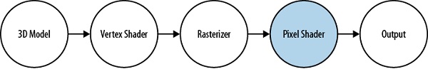
The pixel shader examines each rasterized pixel figure mentioned below, applies the shader algorithm, and gives output the final color value. It includes frequently used additional textures with the original raster image. They excel at color modification and image distortion. If you want to apply a subtle leather texture to an image, the pixel shader is your tool.
The pixel shader in the pipeline is shown in the below image −
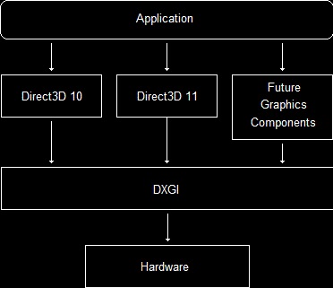
DirectX - Graphics Pipeline
The theme of this chapter is to understand rendering pipeline, also called as Graphics Pipeline. Consider the geometric description of a 3D scene with a positioned and oriented virtual camera which calls the rendering pipeline. This pipeline includes entire sequence of steps necessary to generate 2D images based on what the virtual camera sees.
Before we start understanding the rendering pipeline, we should understand two basic steps −
- 3D Illusion
- Representation of colors which works mathematically
The figure mentioned below includes stages that make up the rendering pipeline. The direction mentioned from the memory pool to stage can access the resources as a specific input.
The best illustration is the pixel shader stage to read data from a texture resource stored in the memory.
The figure includes an arrow going from a stage to memory, i.e., the stage which writes to the mentioned GPU resources. The best example is the output merger stage which is considered as bidirectional. The other example is Vertex shader stage which takes input from data from the Input Assembler stage and generates the output to Geometry Shader stage.
The subsequent sections give an overview of each stage of the rendering pipeline. The sections are namely −
- Buffers
- Textures
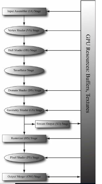
Buffers comprise of Input Assembler, Vertex Shader and Hull Shader stages. The other stages are included within the section of textures. It also includes stream output stage which is depicted in the snapshot above. This stage gives respective output to the user. The description of all stages are described in later sections of this tutorial.
DirectX - Buffers
For the GPU to access an array of vertices, they need to be placed in a special resource structure called a buffer, which is represented by the ID3D11Buffer interface.
A buffer that stores vertices is called a vertex buffer. Direct3D buffers not only store data, but also describe how the data will be accessed and where it will be bound to the rendering pipeline.
Indices and Index Buffers
Because indices need to be accessed by the GPU, they need to be placed in a special resource structure an index buffer. Creating an index buffer is very similar to creating a vertex buffer, except that the index buffer stores indices instead of vertices. Therefore, rather than repeating a discussion similar to the one carried out for vertex buffers, we just show an example of creating an index buffer −
UINT indices[24] = {
   0, 1, 2, // Triangle 0
   0, 2, 3, // Triangle 1
   0, 3, 4, // Triangle 2
   0, 4, 5, // Triangle 3
   0, 5, 6, // Triangle 4
   0, 6, 7, // Triangle 5
   0, 7, 8, // Triangle 6
   0, 8, 1 // Triangle 7
};
// Describe the index buffer we are going to create. Observe the
// D3D11_BIND_INDEX_BUFFER bind flag
D3D11_BUFFER_DESC ibd;
ibd.Usage = D3D11_USAGE_IMMUTABLE;
ibd.ByteWidth = sizeof(UINT) * 24;
ibd.BindFlags = D3D11_BIND_INDEX_BUFFER;
ibd.CPUAccessFlags = 0;
ibd.MiscFlags = 0;
ibd.StructureByteStride = 0;
// Specify the data to initialize the index buffer.
D3D11_SUBRESOURCE_DATA iinitData;
iinitData.pSysMem = indices;
// Create the index buffer.
ID3D11Buffer* mIB;
HR(md3dDevice->CreateBuffer(&ibd, &iinitData, &mIB));
As with vertex buffers, and other Direct3D resources for that matter, before we can use it, we need to bind it to the pipeline. An index buffer is bound to the input assembler stage with theID3D11DeviceContext::IASetIndexBuffer method.
Following is an example call −
md3dImmediateContext->IASetIndexBuffer(mIB, DXGI_FORMAT_R32_UINT, 0);
DirectX - 3D Transformation
In this chapter, we will focus more on transformations which help us change the 3D model coordinates to respective pixel coordinates.
Types of Transforms
There are three basic types of transforms −
- World Transform
- View Transform
- Projection Transform
World Transform
Direct3D uses these transformation models to include translations, rotations and scaling. The only condition here is that it does not apply to lights.
View Transform
View transform mainly focuses on the transition of world coordinates to the respective camera space determining the position of camera.
Projection Transform
Projection transform is usually designed to change the geometry perspective from camera space into clip space and applies the respective transform.
Clipping and transforming vertices usually take place in homogenous space but the final result for most applications needs to be three-dimensional (3D) non-homogenous coordinates defined in "screen space". This means that we should put both the input vertices and the clipping volume into the respective homogenous space to perform the clipping and then translate back into non-homogenous space to be displayed.
A Direct3D matrix is defined as a 4x4 homogenous matrix defined by a D3DMATRIX structure. Although Direct3D matrices are not considered as standard objects, they are represented by a COM interface.
The Transformation Pipeline
Consider the vertex mentioned in the coordinate system given by the below equation −
Pm = (Xm, Ym, Zm, 1)
Then, the transformations created as shown in the following figure are applied to compute screen coordinates by the given equation −
Ps = (Xs, Ys, Zs, Ws)
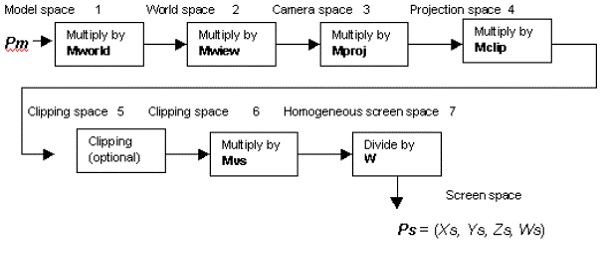
Now let us focus on the description of each transformation stage which is needed.
World matrix Mworld transforms the required vertices from the model space to the world space. This matrix is set as mentioned below −
syntaxCopy
   d3dDevice->SetTransform (D3DTRANSFORMSTATE_WORLD, matrix address)
DirectX assumes that the last column of this matrix is taken as (0,0,0,1). No error is returned if the user specifically mentions the matrix with a different last column.
View matrix Mview transforms vertices from the world space to the camera space. The demonstration of setting up this matrix is set as follows −
syntaxCopy
   d3dDevice->SetTransform (D3DTRANSFORMSTATE_VIEW, matrix address)
Direct3D implementation assumes that the last column of this matrix is (0, 0, 0, 1).
Projection matrix which is also called Mproj transforms vertices from the mentioned camera space to the projection space. The basic syntax of creating the matrix is mentioned below −
syntaxCopy
   d3dDevice->SetTransform (D3DTRANSFORMSTATE_PROJECTION, matrix address)
DirectX - Drawing
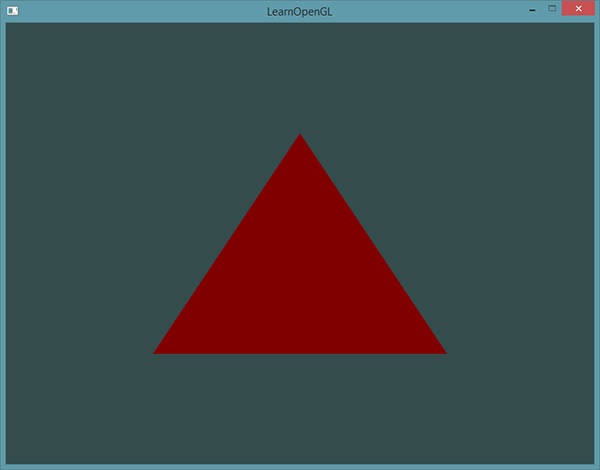
This chapter, in turn, focuses on the Direct3D API interfaces and methods which are needed to configure the rendering pipeline, define vertex and pixel shaders, and submit geometry to the rendering pipeline for drawing. After understanding the chapter, the user should be able to draw various geometric shapes with coloring or in wireframe mode.
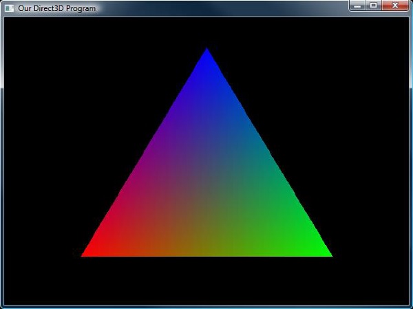
Here, we will focus on drawing a triangle with Direct3D API.
Step 1
In the first step, we include the basic header files, especially Direct3D header files which are required to draw a triangle with the code given below −
#include <windows.h>
#include <windowsx.h>
#include <d3d9.h>
Step 2
In the second step, we define the necessary parameters such as screen resolution, function parameters, and Direct3D library file. Include the global declarations and function prototypes as given in the below code −
#define SCREEN_WIDTH 800
#define SCREEN_HEIGHT 600
#pragma comment (lib, "d3d9.lib")
LPDIRECT3D9 d3d; // the pointer to our Direct3D interface
LPDIRECT3DDEVICE9 d3ddev; // the pointer to the device class
LPDIRECT3DVERTEXBUFFER9 v_buffer = NULL; // the pointer to the vertex buffer
void initD3D(HWND hWnd); // sets up and initializes Direct3D
void render_frame(void); // renders a single frame
void cleanD3D(void); // closes Direct3D and releases memory
void init_graphics(void); // 3D declarations
struct CUSTOMVERTEX {FLOAT X, Y, Z, RHW; DWORD COLOR;};
Step 3
In the next step, we declare the WindowProc function prototype with the required parameters as shown in the below code −
LRESULT CALLBACK WindowProc(HWND hWnd, UINT message, WPARAM wParam, LPARAM lParam);
int WINAPI WinMain(HINSTANCE hInstance, HINSTANCE hPrevInstance,
   LPSTR lpCmdLine, int nCmdShow){

   HWND hWnd;
   WNDCLASSEX wc;
   ZeroMemory(&wc, sizeof(WNDCLASSEX));
   wc.cbSize = sizeof(WNDCLASSEX);
   wc.style = CS_HREDRAW | CS_VREDRAW;
   wc.lpfnWndProc = WindowProc;
   wc.hInstance = hInstance;
   wc.hCursor = LoadCursor(NULL, IDC_ARROW);
   wc.lpszClassName = L"WindowClass";
   RegisterClassEx(&wc);
   hWnd = CreateWindowEx(
      NULL,
      L"WindowClass",
      L"Our Direct3D Program",
      WS_OVERLAPPEDWINDOW,
      0, 0,
      SCREEN_WIDTH, SCREEN_HEIGHT,
      NULL,
      NULL,
      hInstance,
      NULL
   );
   ShowWindow(hWnd, nCmdShow);
}
Step 4
In step 4, we call for the function which initializes the graphics and the necessary parameters as given in the below code −
void init_graphics(void){
   // create the vertices using the CUSTOMVERTEX struct
   CUSTOMVERTEX vertices[] = {
      { 400.0f, 62.5f, 0.5f, 1.0f, D3DCOLOR_XRGB(0, 0, 255), },
      { 650.0f, 500.0f, 0.5f, 1.0f, D3DCOLOR_XRGB(0, 255, 0), },
      { 150.0f, 500.0f, 0.5f, 1.0f, D3DCOLOR_XRGB(255, 0, 0), },
   };
   // create a vertex buffer interface called v_buffer
   d3ddev->CreateVertexBuffer(
      3*sizeof(CUSTOMVERTEX),
      0,
      CUSTOMFVF,
      D3DPOOL_MANAGED,
      &v_buffer,
      NULL
   );
   VOID* pVoid; // a void pointer
   // lock v_buffer and load the vertices into it
   v_buffer->Lock(0, 0, (void**)&pVoid, 0);
   memcpy(pVoid, vertices, sizeof(vertices));
   v_buffer->Unlock();
}
The output generated is mentioned below −
DirectX - Rendering
Once the process of initialization and the swap chain is created, it is time to start rendering the objects. Rendering is considered to be a very easy process with little preparation.
In this chapter, we will be creating a blank frame with specific color which is being used over the period of time.
Following steps are involved for the rendering process in DirectX objects −
Setting the Render Target
Once the user has created the render target, it has to be set as the active render target. This is mandatory for each frame.
The sample function which renders a single frame of 3D graphics is mentioned below −
void CGame::Render(){
   // set our new render target object
   devcon->OMSetRenderTargets(1, rendertarget.GetAddressOf(), nullptr);
   // switch the back buffer
   swapchain->Present(1, 0);
}
The above mentioned function was created to render the active target in more precise manner. If you observe, it includes the below two parameters.
1st parameter
It includes the number of render targets to set.
2nd parameter
It is considered as a pointer to list render target view objects. We only use one parameter to address the render target interface. This particular interface is obtained with the help of GetAddressOf() function. This function is little different in comparison to Get() function. It refers pointer to a pointer instead of just one pointer.
3rd parameter
It is considered as an advanced parameter which will be discussed later. For now, let us consider it to be nullptr.
Clearing the Back Buffer
We will create a function that renders a particular single frame by setting the entire buffer which is black in color.
// this function renders a single frame of 3D graphics
void CGame::Render(){
   // set our new render target object as the active render target
   devcon->OMSetRenderTargets(1, rendertarget.GetAddressOf(), nullptr);
   float color[4] = {0.0f, 0.2f, 0.4f, 1.0f};
   devcon->ClearRenderTargetView(rendertarget.Get(), color);
   swapchain->Present(1, 0);
}
The ClearRenderTargetView() function as discussed in the code snippet above sets each pixel in a render target to a specific color.
1st parameter
It is used to address the render target interface.
2nd parameter
It is used as an array of four float values. The first is red, the second one is green and the third one is considered blue while the fourth is considered with parameter of transparency.
Note − Each value used in the float array is between 0.0f which means no color, and 1.0f which means full color. With this combination, a user can create any color.
DirectX - Modeling
Source assets which is required for models stored in Autodesk FBX, Wavefront OBJ or other formats. A typical build process is used for conversion which is used in run-time friendly format which is easy to load and render.
For creating a model, Visual Studio includes a built-in system which includes a convert format of a Wavefront OBJ or Autodesk FBX which is considered as a part of the build process which is needed to CMO.
In this chapter, we will make use of the DirectXMesh meshconvert command line tool. The developer can start this activity by saving cup.obj, cup.mtl and cup.jpg into the project directory.
Implementing the Modeling
Following steps are required to implement the modeling −
Step 1
Download the Meshconvert.exe from the official site and save the executable file into the users project folder.
Step 2
Open the required command prompt and then change the projects directory. Run the following command executed in below command prompt −
meshconvert cup._obj -cmo -nodds -flipz -y
With this, you can initiate a model creation. Now let us focus on updating effects settings on the mentioned model.
The model class creates the required effects automatically for the loaded materials which are set to lighting parameters. The updating procedure is possible with the Model::UpdateEffects method.
Updating Effects Settings
Following are the steps required to update effects settings in a specific model −
Step 1
From the drop-down menu, select Project/Properties. Set to "All Configurations"/"All Platforms". On the left-hand tree view, select C/C++ Language. Then set "Enable Run-Time Type Information" to "Yes". Click "OK".
Step 2
In the mentioned file Game.cpp, add the TODO of CreateDevice as shown below −
m_model->UpdateEffects([](IEffect* effect){
   auto lights = dynamic_cast<IEffectLights*>(effect);
   if (lights){
      lights->SetLightingEnabled(true);
      lights->SetPerPixelLighting(true);
      lights->SetLightEnabled(0, true);
      lights->SetLightDiffuseColor(0, Colors::Gold);
      lights->SetLightEnabled(1, false);
      lights->SetLightEnabled(2, false);
   }
   auto fog = dynamic_cast<IEffectFog*>(effect);
   if (fog){
      fog->SetFogEnabled(true);
      fog->SetFogColor(Colors::CornflowerBlue);
      fog->SetFogStart(3.f);
      fog->SetFogEnd(4.f);
   }
});
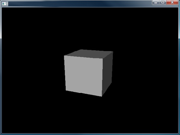
The above code is designed to build and run our cup with the colored light, per pixel rather than vertex lighting and the fogging was enabled.
DirectX - Lighting
DirectX is known for creating lights which is similar to real world lighting. It includes a system of varied calculation which is less time consuming and demonstrates the real world system. Lighting is considered as an important part of 3D game programming. Lighting helps user to bring the realism out and make it as a real time experience. The DirectX system includes built up of various set of types like lightning and types of light sources. Now, it is important to focus on three types of lightning as mentioned below −
- Diffuse Lighting
- Ambient Lighting
- Specular Lighting
Diffuse Lighting
Diffuse light is a dim light which falls on the surface. The best demonstration is a user holding up hand with this light source. It will be visible that one side of hand is lit while the other side is not. The side which is lit is called as diffuse light and the procedure is called diffuse lighting.
Ambient Lighting
Ambient light refers to the light which spreads everywhere. As per the previous example, holding up the arm with one light source, the dark side is called as lightly lit or ambient lit. The light which is reflected is considered as ambient light and the process is called as ambient lighting.
Specular Light
Specular light is also called as specular highlight or even more commonly as reflection. When light reflects off the required object, usually most of the light will go in one specific direction.
Creating Lights
This section includes the process of creating lights which is often used for creating lights. Following are the important steps needed for creating lights −
- Starting with new flexible format
- Process of turning light on
- Ambient light setup
- Diffuse light setup
- Setting the material standards
The first three are considered as simple processes, but the last two will require a whole function to themselves.
Starting with new flexible format
Once again, we will focus on the FVF code and the vertex format will change. This time we are focusing on the diffuse color and add a new property in the vertex normal. The new FVF code and vertex format is mentioned below −
struct CUSTOMVERTEX {FLOAT X, Y, Z; D3DVECTOR NORMAL;};
#define CUSTOMFVF (D3DFVF_XYZ | D3DFVF_NORMAL)
D3DVECTOR NORMAL;
#definition of the structure
typedef struct D3DVECTOR {
   float x, y, z;
} D3DVECTOR, *LPD3DVECTOR;
Process of turning light on
The function call is already discussed in the previous sections. The process of activating the lights on is given in the following code −
d3ddev->SetRenderState(D3DRS_LIGHTING, TRUE);
Ambient Light setup
This step uses the same particular function, SetRenderState which is considered as the first parameter that changes to a different flag, the second parameter is D3DRS_AMBIENT which is color of the ambient light.
d3ddev->SetRenderState(D3DRS_AMBIENT, D3DCOLOR_XRGB(50, 50, 50)); // ambient light
Diffusion of light setup
This step is longer than normal. It is important for the properties of the size and flexibility of this step, with its own function called own_light(). It is given below −
this is the function that sets up the lights and materials
void init_light(void){
   D3DLIGHT9 light; // creating the structure of light
   ZeroMemory(&light, sizeof(light)); // following zero memory pattern
   light.Type = D3DLIGHT_DIRECTIONAL; // creating the light type
   light.Diffuse = D3DXCOLOR(0.5f, 0.5f, 0.5f, 1.0f); // setting up the color
   light.Direction = D3DXVECTOR3(-1.0f, -0.3f, -1.0f);
   d3ddev->SetLight(0, &light); // send the light struct properties to light #0
   d3ddev->LightEnable(0, TRUE); // turn on light #0
}
D3DLIGHT9
D3DLIGHT9 is a struct data which includes all the information about a light, no matter what its type is.
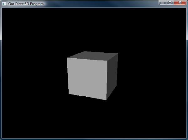
The demonstration of the lit cube is mentioned below −
DirectX - Texturing
A texture resource is considered as a core part of gaming programming. It includes structured collection of data which is designed to store texels. Texel represents the smallest unit of a texture which can be read or written with the help of pipeline. Textures can be filtered by texture samplers as they are read by shader units. The texel includes 1 to 4 components which are arranged in DXGI formats. These textures are created as a structured resource with the mentioned size. The texture can be considered as typed or typeless based on the resource that is being created.
Now let us focus on the texture types which are primarily used by DirectX. Different textures are mentioned below −
- 1D Textures
- 1D Texture Arrays
- 2D Textures and 2D Texture Arrays
- 3D Textures
1D Textures
A 1D texture is the simplest form which contains texture data with only one base coordinate.
For DirectX, 1D textures are represented by the ID3D11Texture1D interface. Each texel contains a number of color components which is based on the data being stored.
A mipmap level in 1D texture that is a power-of-two smaller than the level above it.
Now let us focus on 1D Texture Arrays which is described below
1D Texture Arrays
This includes collection of 1D texture arrays. Direct3D 11 also supports arrays of textures. A 1D texture array is represented by the ID3D11Texture1D interface speaking in terms of DirectX latest version.
An array of 1D textures looks conceptually like the following illustration −
The texture array with one dimension consists of three textures. Each of the three textures has a texture with a width of 5 elements. Each texture also consists of layer with 3 tiers mipmap.
2D Textures and 2D Texture Arrays
A Texture2D is a 2 dimensional figure which consists of a 2D grid of texels. Each texel is usually addressed by a u, v vector. The texture resource, it consists mipmap levels and sub resources. 2D textures are represented in DirectX with respect to ID3D11Texture2D interface. The snapshot below depicts the 2D textures which is primarily used in gaming programming activities.
A 2D texture array is a collection of 2D textures which includes resource with a composition of homogeneous array of 2D textures where each texture includes the same data format and dimensions.
3D Textures
A 3D texture resource also referred with other name volume texture resource contains a 3D volume of texels. It includes minimap levels as it is texture resource. 3D textures in DirectX are implemented by the ID3D11Texture3D interface. A fully populated 3D texture looks like the way it is represented in snapshot below −
3D texture mipmap slice includes a constraint with render target output also with respect to render target view, the 3D texture includes behaviour is considered identical to 2D texture array.
DirectX - Multi Texturing
DirectX includes the blend of eight textures onto primitives with respect to single iteration. The usage of multiple texture blending is used to increase the frame rate. An application includes a pattern of multiple texture blending to apply various textures and shadows with various lighting formats which is called as specular lighting and diffuse lighting.
To use texture blending, the application should be first evolved. This information is found in the TextureCaps member of DirectX which includes D3DCAPS9 structure.
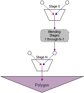
Texture Stages and the Texture Blending Cascade
Direct3D supports single-pass multiple texture which includes blend of texture stages. A texture stage takes two parameters and performs a blending operation on them, passing the particular result for processing or rasterization. The visualization of texture stage is visible in the following diagram −
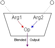
As per the snapshot mentioned above, texture stages include blend of two arguments by using a specified operator. Common operations include simple modulation or addition of the color or alpha components of the arguments with respect to two dozen operations are supported. The arguments for mentioned stage can be an associated texture, the iterated color or alpha, arbitrary color and alpha stages.
Note − DirectX distinguishes the required color blending from alpha blending. Applications include the set blending operations and arguments which are needed for color and alpha individually, and the results of those settings are actually interdependent on each other.
The combination of arguments and operations are usually used by multiple blending stages which define a simple flow-based blending language. The results are gathered as one stage flow down to another respective stage and so on. The concept of results flowing from one stage to another stage is eventually be rasterized on the mentioned polygon and is often called the texture blending cascade. The following snapshot shows how the respective individual texture stages make up the texture blending cascade.
The description of the diagram with respect to the above mentioned diagram is implemented below −
DirectX includes eight blending stages which helps to check the device capabilities. Each stage in a device has a zero-based index.
The first blending stage is referred as index 0, the second as 1 and the count goes up to index 7.
The system includes stages in increasing index order.
The system includes blends of the respective two stages and ignores the required stages.
Note − DirectX should implement all the respective stages to create a well-defined multi textured component.
DirectX - Blending
DirectX includes a blending property which defines the combination of creation from the existing one. Consider that there are two sources namely: Source 1 and Source 2 where Source 1 refers to the data source for source pixel blending factor and Source 2 is the data source for destination pixel blending factor. DirectX does the blending in such a way that the source pixel is always the fragment coming from the pixel shaders output and the destination pixel is always the pixel from the current active render target.
DirectX from version 1 has a blend state structure: ID3D10BlendState which is a standalone structure which describes the state of the flow chart or rather the mentioned sources. To create this blend state, the user needs to first fill out a D3D10_BLEND_DESC structure which describes the various options of the blend state. This seems to be confusing as SDK docs mention different documentation states of D3D10_BLEND_DESC.
The simple structure is mentioned in the code below −
struct D3D10_BLEND_DESC{
   BOOL AlphaToCoverageEnable;
   BOOL BlendEnable[8];
   D3D10_BLEND SrcBlend;
   D3D10_BLEND DestBlend;
   D3D10_BLEND_OP BlendOp;
   D3D10_BLEND SrcBlendAlpha;
   D3D10_BLEND DestBlendAlpha;
   D3D10_BLEND_OP BlendOpAlpha;
   UINT8 RenderTargetWriteMask[8];
}
The factors to work on or rather the parameters which are included with required explanation are mentioned below −
SrcBlend − This blend option is used as the source blending factor data source and consists of an optional pre-blend operation.
DestBlend − This blend option includes the destination blending factor data source and a pre-blend operation.
SrcBlendAlpha − This blend option specifies the source alpha blending factor data source and includes an operation of pre-blending situation. Blend options which end in _COLOR are usually not considered.
DestBlendAlpha − This blend option specifies the destination alpha blending factor data source and includes an optional pre-blend operation. Blend options which end in _COLOR are usually not considered.
There are two more parameters (SrcBlendAlpha & DestBlendAlpha) which actually define the blending factors for the source and destination alpha channels. The blending of the alpha values is done in a complete different format from the blending of color values. Now, it is important that user should use your final image as a flat bitmap.
Creating the custom blend state is explained perfectly below −
ID3D10BlendState* g_pBlendState = NULL;
D3D10_BLEND_DESC BlendState;
ZeroMemory(&BlendState, sizeof(D3D10_BLEND_DESC));

BlendState.BlendEnable[0] = TRUE;
BlendState.SrcBlend = D3D10_BLEND_SRC_ALPHA;
BlendState.DestBlend = D3D10_BLEND_INV_SRC_ALPHA;
BlendState.BlendOp = D3D10_BLEND_OP_ADD;
BlendState.SrcBlendAlpha = D3D10_BLEND_ZERO;
BlendState.DestBlendAlpha = D3D10_BLEND_ZERO;
BlendState.BlendOpAlpha = D3D10_BLEND_OP_ADD;
BlendState.RenderTargetWriteMask[0] = D3D10_COLOR_WRITE_ENABLE_ALL;

pd3dDevice->CreateBlendState(&BlendState, &g_pBlendState);
In the above mentioned code snippet, blendState is used frequently in every line. It is really simple to understand the OMSetBlendState function of our D3D device. This sets up the blending stage to the state that we have described in our blend state object.
pd3dDevice->OMSetBlendState(g_pBlendState, 0, 0xffffffff);
The first parameter is obviously considered as the blend state. The second is an array of blend factors to use in special case which is used as color channel blending; while the third parameter includes a sample mask which defines bits to be written during blending with respect to render targets.
DirectX - Picking
The traditional method which is needed to perform the action of picking relies on the technique is called ray-casting. The user can shoot a ray from the camera position through the selected point which the aspect of near plane of the required frustum which intersects the resulting ray. The first object intersected by the way is considered as the ray of object which is picked.
We will be creating the Picking Demo project as mentioned in the figure below −
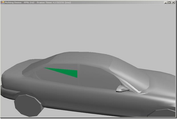
Here, you can see that only the required part is hand-picked or the picking process is created.
To pick the respective object, the user should convert the selected screen pixel into the mentioned cameras view space. The screen-space coordinate is used to view the required space with the conversion of pixel position. Now let us focus on the process of picking the ray. The ray starts with the given point and extends the direction until it reaches the point of infinity. The specialized class called SlimDX provides the required position and the maintained direction properties which is referred to as intersection tests with bounding boxes, spheres, triangles and planes.
Normalized Device Coordinates
Normalized device coordinates map the screen with respect to x and y coordinates within the range of [-1,1].
The parameters which are used for transformation into the required world space by transforming the origin to the mentioned direction of vectors include ray with the inverse of cameras view matrix. The code snippet which can be used is mentioned below −
public Ray GetPickingRay(Vector2 sp, Vector2 screenDims) {
   var p = Proj;
   // convert screen pixel to view space
   var vx = (2.0f * sp.X / screenDims.X - 1.0f) / p.M11;
   var vy = (-2.0f * sp.Y / screenDims.Y + 1.0f) / p.M22;
   var ray = new Ray(new Vector3(), new Vector3(vx, vy, 1.0f));
   var v = View;
   var invView = Matrix.Invert(v);
   var toWorld = invView;
   ray = new Ray(Vector3.TransformCoordinate(ray.Position, toWorld),
      Vector3.TransformNormal(ray.Direction, toWorld));
   ray.Direction.Normalize();
   return ray;
}
Picking an Object in the 3D Scene
Now we will focus on picking the object with respect to the 3D scene to select a triangle from our car mesh in this example. This changes our OnMouseDown override slightly, consider the code snippet which is mentioned below −
protected override void OnMouseDown(object sender, MouseEventArgs mouseEventArgs) {
   if (mouseEventArgs.Button == MouseButtons.Left) {
      _lastMousePos = mouseEventArgs.Location;
      Window.Capture = true;
   }
   else if (mouseEventArgs.Button == MouseButtons.Right) {
      Pick(mouseEventArgs.X, mouseEventArgs.Y);
   }
}
DirectX - Stenciling
Applications which use gaming programming usually use the stencil buffer to mask the respective pixels. Some of the common effects of stenciling which are implemented in DirectX are mentioned below −
- Compositing
- Decaling
- Dissolves, Fades, and Swipes
- Outlines and Silhouettes
- Two-Sided Stencil
The stencil buffer in DirectX helps user to enable or disable the drawing patterns to the rendering target surface on pixel-by-pixel basis. The most fundamental level included is enabling the applications to mask sections of the required rendered image which is clearly not depicted. Applications usually use stencil buffers with required special effects and activities such as dissolves, decaling, and outlining.
Stencil buffer information in DirectX is embedded in z-buffer data which is called z coordinate area. The application can use the IDirect3D9::CheckDeviceFormat method to check for hardware stencil support, as mentioned in the code snippet below −
if( FAILED( m_pD3D->CheckDeviceFormat( pCaps->AdapterOrdinal,
   pCaps->DeviceType,
   Format,
   D3DUSAGE_DEPTHSTENCIL,
   D3DRTYPE_SURFACE,
   D3DFMT_D24S8 ) ) )
return E_FAIL;
IDirect3D9::CheckDeviceFormat interface of DirectX allows user to choose a device to create the capabilities of the device. In this situation, devices that do not support 8-bit stencil buffers are rejected.
Working of the Stencil Buffer
Direct3D performs a particular test with the contents of the required stencil buffer on a pixel-by-pixel basis. Every pixel is considered strong with respect to the target surface, includes performing the test for corresponding value in the stencil buffer, a stencil reference value, and a stencil mask value. Direct3D performs an action. The test is performed using the following steps −
Perform a bitwise AND operation of the stencil reference value with the stencil mask of DirectX.
Perform the same operation with current pixel with the stencil mask.
Compare the results generated, using the comparison function.
The current pixel is always written to the target surface if the particular test is successful, and is completely ignored if the test fails. The default comparison behavior is usually written in the pixel, no matter how the bitwise operation turns out is called as D3DCMP_ALWAYS.
The application can usually customize the operation of the stencil buffer which is great functionality of stencil buffer. It can be set as the comparison function, the stencil mask, and the stencil reference value. It usually controls the action that Direct3D or DirectX takes when a particular stencil test passes or fails.
Illustrations
The following code examples are usually considered to demonstrate setting up the stencil buffer −
// Enable stencil testing
pDevice->SetRenderState(D3DRS_STENCILENABLE, TRUE);

// Specify the stencil comparison function
pDevice->SetRenderState(D3DRS_STENCILFUNC, D3DCMP_EQUAL);

// Set the comparison reference value
pDevice->SetRenderState(D3DRS_STENCILREF, 0);

// Specify a stencil mask
pDevice->SetRenderState(D3DRS_STENCILMASK, 0);

// A write mask controls what is written
pDevice->SetRenderState(D3DRS_STENCILWRITEMASK, D3DSTENCILOP_KEEP);

// Specify when to write stencil data
pDevice->SetRenderState(D3DRS_STENCILFAIL, D3DSTENCILOP_KEEP);
By default, the stencil reference value is zero. Any integer value is valid. DirectX performs a bitwise AND of the stencil reference value and a stencil mask value before the stencil test.
The user can control what pixel information is written out depending on the stencil comparison.
DirectX - First Shader
This chapter gives an overview of Shader which is written in HLSL. Integrating the shader with respect to DirectX is the core concept which is covered in this chapter. Types of shaders include −
- Vertex Shader
- Pixel Shader
A Shader is a small code snippet that completely runs on the graphics processor and is therefore considered very fast. DirectX supports shaders and its implementation since version 8.0. The first support started with Vertex and Pixel Shaders written in Assembler language.
In DirectX 9, High Level Shader Language (HLSL) was later added, which helped programming in C-like language. From version 10, it includes features of Geometry Shader and DirectX 11 extended to the implementation of Compute Shader.
After DirectX10, Shader is considered as the primary focus of DirectX as it includes Fixed Rendering Pipeline which was removed from the scratch. In other words, if a user likes to have an appealing result using DirectX, user will automatically use them. It is possible to create beautiful surface effects, animations and other things which can be seen within the mentioned surface area.
This chapter will focus on vertex shader and the next chapter on pixel shader.
Vertex Shader
The Vertex Shader is designed as per one vertex which takes it as an input, processes it, and then returns the value to DirectX Pipeline. The Vertex Shader is considered as the first Shader for the mentioned Pipeline and gets the data in combination with input and assembler. Mainly vertex shader helps in transforming and illuminating the calculations for special effects which are considered possible.
Below is the structure of a simple Vertex Shader −
Like in C programming language, the vertex data can be packaged together in a particular structure. DirectX receives the data mapping identifiers called Semantics, so that DirectX knows which data can be processed and which should be assigned to the required variables. The Semantic starting with SV is referred as System Value Semantic, while the one provided with system declaration is always taken through the DirectX pipeline. The input and output data can be considered different on a Vertex Shader in comparison to all shaders.
In the snapshot mentioned above, normal and texture coordinates are passed to the Shader and after processing in the Shader, the vertex position is treated with respect to world coordinates which is returned in addition to the transformed data. It includes its own data types in the DirectX with reference to the DirectX SDK which can be considered mandatory.
The following points should be kept in mind before proceeding with it −
Variables must be passed with respect to the shader with resource objects.
There are several types of objects which can be included namely: cBuffer, tBuffer, Texture2D and Texture2DArray.
The position of each vertex is transformed as the Vertex Shader with the combination of world matrix.
The meaning of the normal and the position in world coordinates becomes crystal clear when user tries to implement Pixel Shader.
DirectX - Pixel Shader
The Pixel Shader is called once per pixel in comparison to vertex shader which it calls as per vertex and gets its data from the preceding pipeline station respectively from the preceding Shader. It calculates the required pixel color (pixel depth or any other values are possible) and returns them to the required pipeline.
The Pixel Shader is considered as the last Shader in the pipeline and therefore already gives the data to the Output Merger, which helps us to determine the final pixel color. Pixel Shaders are prominently used for rendering surfaces but in comparison to shaders, they can be used for special calculations. The two most important ways to use them include texturing and lighting, for which we will focus on the example following the pixel shader representation or structure.
Structure of a Pixel Shader
In principle with reference to snapshot given below, you will find there is no real difference to a Vertex Shader, only the input and output data is different.
Texturing and lighting with a Pixel Shader
The following code demonstrates how texturing and lighting with a Pixel Shader is done −
struct PixelShaderInput{
   float4 position : SV_POSITION;
   float3 outVec : POSITION0;
   float3 normal : NORMAL0;
   float3 light : POSITION1;
};
float4 main(PixelShaderInput input) : SV_TARGET{
   float3 L = normalize(input.light);
   float3 V = normalize(input.outVec);
   float3 R = normalize(reflect(L, input.normal));
   float4 diffuse = Ka + (lightColor * Kd * max(dot(input.normal, L), 0.0f));
   diffuse = saturate(diffuse);
   float4 specular = Ks * pow(max(dot(R, V), 0.0f), shininess.x - 50.0f);
   specular = saturate(specular);
   float4 finalColor = diffuse + specular;
   return finalColor;
}
The buffer includes the light position in world coordinates which is created and a texture with reference to sampler is always used. The Sampler is mandatory to read the texture color on the corresponding texture coordinates. The Pixel Shader includes the input data received from the Vertex Shader which is interpolated by DirectX. This means with reference to the current pixel from the three vertices of the current triangle we can draw, distance- and mode-dependent "averages" are calculated.
DirectX - Geometry Shaders
The geometry-shader (GS) stage completely runs application-specified shader code with vertices taken as an input to create the ability to generate vertices which is mentioned as output.
The Geometry Shader
Unlike vertex shaders which operate on a single vertex, the geometry shader's inputs are the vertices which include full primitive with two vertices for lines, three vertices for triangles and single vertex for the mentioned point. Geometry shaders can also bring together in the vertex data for the edge-adjacent primitives which is considered as input.
The following illustration of geometry shader shows a triangle and draws a line with adjacent vertices −
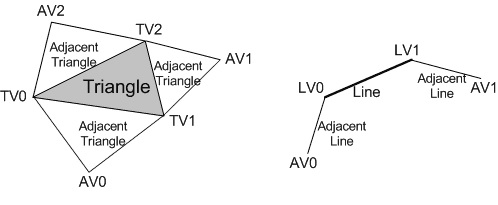
The abbreviated forms of various geometrical shaders are mentioned below −
| Abbreviated Form | Meaning |
|---|---|
| TV | Triangle vertex |
| AV | Adjacent vertex |
| LV | Line vertex |
The geometry shaders consumes more space with respect to SV PrimitiveID which allows per primitive data to be fetched or completed which is needed.
The geometry-shader stage includes the capability of creating the outputs of multiple vertices forming a single selected topology. The number of primitives which is emitted can include number of vertices which can be emitted statically. It includes strip lengths which can be created with the help of required function.
Geometry shader creates an output which is fed to rasterizer stage and/or to a vertex buffer in memory with the help of stream output stage. Output fed to the mentioned memory is always expanded to individual point/line/triangle lists.
When a geometry shader is always considered as active, it is invoked once for every primitive passed down or generated with respect to pipeline. Each invocation of the respective geometry shader should include the input of the required data for invoking primitive, whether that is a single point, a single line, or a single triangle.
A triangle strip from earlier mentioned pipeline would result in the invocation of the geometry shader for mentioned individual triangle as in the strip.
Various types of algorithms that can be implemented in the geometry shader include −
- Point Sprite Expansion
- Dynamic Particle Systems
- Fur/Fin Generation
- Shadow Volume Generation
- Single Pass Render-to-Cubemap
The code snippet for the implementation of geometry shader in comparison to pixel shader or vertex shader is mentioned below −
PrimitiveType DataType Name [ NumElements ]
point VS_OUTPUT input[1] // Point of single element,
line VS_OUTPUT input[2] // Output with second element
line adj VS_OUTPUT input[4]
triangle VS_OUTPUT input[3]
triangle adj VS_OUTPUT input[6]
DirectX - Compute Shaders
In 3D programming, compute shader is a programmable shader stage which calls for the respective buffer. It expands the feature of Microsoft Direct3Dt3d version 11. The shader technology which is included is DirectCOMPUTE technology.
Like vertex and geometry which we discussed in the last chapter, a compute shader is designed and implemented with HLSL where many similarities can be tracked. A compute shader includes high-speed general purpose computing and includes advantage of various large numbers of parallel processors on the graphics processing unit (GPU).
The compute shader includes memory sharing and thread synchronization features which allows more effective parallel programming methods when developer calls the ID3D11DeviceContext::Dispatch or ID3D11DeviceContext::DispatchIndirect method to execute commands in a compute shader.
Implementation of Compute Shader on Direct3D 10.x Hardware
A compute shader from Microsoft Direct3D 10 is also considered as DirectCompute 4.x.
If a user calls Direct3D 11 API and updated drivers, feature level 10 and 10.1 Direct3D hardware can equally support the required form of DirectCompute that uses the cs_4_0 and cs_4_1 profiles.
When user computes DirectCompute on this hardware, following points should be considered in mind −
The maximum number of threads should be limited to GROUP (768) per group.
The X and Y dimension of numthreads is limited to to size of 768.
The Z dimension of numthreads is always limited to 1.
The Z dimension of dispatch is limited with respect to D3D11_CS_4_X_DISPATCH_MAX_THREAD_GROUPS_IN_Z_DIMENSION (1).
Only one shader view can be bound to the shader (D3D11_CS_4_X_UAV_REGISTER_COUNT is 1).
The respective buffers namely RWStructuredBuffers and RWByteAddressBuffers are usually available as unordered-access views. A thread can only access the required region with respect to group shared memory for writing.
SV_GroupIndex or SV_DispatchThreadID is used while accessing a particular group of elements for computing shader. Groupshared memory is usually limited to 16KB per group.
A single thread is limited to 256 byte region of groupshared memory for writing.
Compute Shader on Direct3D 11.x Hardware
A compute shader on Direct3D 11 is termed as DirectCompute 5.0.
When user uses a DirectCompute interface with cs_5_0 profiles, following points should be kept in mind −
The maximum number of threads is limited to (1024) per group. The count is increased 1024.
The X and Y dimension of numthreads is limited to 1024.
The Z dimension of numthreads is limited to 64.
The basic code snippet of creating a compute shader is given below −
ID3D11ComputeShader* g_pFinalPassCS = NULL;
pd3dDevice->CreateComputeShader( pBlobFinalPassCS->GetBufferPointer(),
   pBlobFinalPassCS->GetBufferSize(), NULL, &g_pFinalPassCS );
DirectX - Shader Effects
This chapter will include an illustration of various shader effects which most 2D games use with respect to sprites. Most 2D effects are created with the help of fragment shaders. The main goal here is to create a simple effect with respect to the secondary texture to modify the original color. This type of shading effect is called as ToonShading.
If the original image has a color combination red/green/blue values of black (0, 0, 0), the user will look at 0% inside the color ramp and see (1.0, 1.0, 1.0) (switching black to white). We will be performing following steps to analyze the shader effect of printing Hello World which is mentioned below −
The user will be working with three color components (red, green and blue), expressed as a percentage between 0 and 1. If the user has used a range between 0-255, just divide what has been used by 255.
Notice how the type of image gets changed with color combination (RGB 0.0, 0.0, 0.0) to black (RGB 1.0, 1.0, 1.0). For each RGB value in the original image, we are going to look up the corresponding entry in this color mask, effectively reversing the color of the original image.
If the original image has a red/green/blue value of white (1.0, 1.0, 1.0), the user will look at it as 100% inside the color ramp and see (0, 0, 0).
If the original image has a red/green/blue value of the yellow in the Cocos2D logo, the user will look at the corresponding file sizes for each component inside the color ramp and see (0.01, 0.28, 0.58).
Also, since the color ramp is only 64 pixels wide, it will result in a smaller range of color values than the original image, resulting in a banding effect.
Consider a new file which is created in our project folder. Create a subclass of CCLayer and save the class as CSEColorRamp.
Create HelloWorldLayer.m and import CSEColorRamp.h at the top of the file as follows −
#import "CSEColorRamp.h"
Then replace the existing code for HelloWorldLayers init method with the following code −
// Initialize the hello world layer
-(id) init {
   if( (self=[super init])) {
      CCLabelTTF *label = Hello World" fontName:@"Marker Felt" fontSize:64;
      CGSize size = [[CCDirector sharedDirector] winSize];
      label.position = ccp( size.width /2 , size.height/2 );
      [self addChild: label];
      [CCMenuItemFont setFontSize:28];
      CCMenuItem *itemColorRamp = [CCMenuItemFont itemWithString:@"Color Ramp" block:^(id sender) {
         CCScene *scene = [CCScene node];
         [scene addChild: [CSEColorRamp node]];
         [[CCDirector sharedDirector] pushScene:scene];
      }];
      CCMenu *menu = [CCMenu menuWithItems:itemColorRamp, nil];
      [menu alignItemsHorizontallyWithPadding:20];
      [menu setPosition:ccp( size.width/2, size.height/2 - 50)];
      [self addChild:menu];
   }
   return self;
}
Compile and run the app, and you will see the following output −

DirectX - Quaternion
The rotations of every graphic element are done with the help of xwing as per the rotations around the 3D axis, i.e., X, Y and Z axis. Xwing is something which is considered as a unique feature of rotating a particular object in quaternion. The only problem here is that it includes same dimensions with respect to matrices. For such a situation, a user or a developer will need a particular solution which would solve the problem.
Deriving a total rotation from the mentioned 3 separate values of each axis with reference to trigonometric formulae is something which should be discussed and it is included in further analysis.
Quaternion is matrix like structure which provides only one rotation. A quaternion is considered to be very easy to use from developer point of view. Consider for the following examples where where we declare vectors with mentioned below which describes the standard syntax −
Vector3 xwingPosition = new Vector3(18, 11, -3);
#Vector definition with three co-ordinates
Quaternion xwingRotation = Quaternion.Identity;
#Creation of identity with respect to rotation
Consider the CreateModel method where the user can change the world matrix for our xwing, with respect to correct location, and correct rotation −
Matrix worldMatrix = Matrix.CreateScale(0.07f, 0.0015f, 0.12 f)
   * Matrix.CreateRotationY(MathHelper.Pi)
   * Matrix.CreateTranslation(xwingPosition);
The mentioned code seems to be complex, but it is quite easy.
The mesh is translated to its correct position with the help of matrix.
The xwing is rotated among the rotation stored in the xwingRotation quaternion.
Once the above steps are achieved, it is rotated along 180 degrees to compensate the opposite direction stored inside the model. And finally, the model is scaled down so it fits nicely in our scene.
The code snippet for creating a dimension of camera is mentioned below −
private void UpdateCamera() {
   Vector3 campos = new Vector3(0, 0.1f, 0.6f);
}
The sample code which is created is mentioned below −
D3DXQUATERNION qZ;
   D3DXQUATERNION qY;
   D3DXQUATERNION qX;
   D3DXQUATERNION qOrient;
   D3DXQUATERNION qTotal;
   D3DXQuaternionIdentity(&qZ);
   D3DXQuaternionIdentity(&qY);
   D3DXQuaternionIdentity(&qX);
   D3DXQuaternionIdentity(&qOrient);
   D3DXVECTOR3 axisZ(0,0,1);
   D3DXVECTOR3 axisY(0,1,0);
   D3DXVECTOR3 axisX(1,0,0);
   D3DXQuaternionRotationAxis(&qZ,&axisZ,ga->getRotation().z);
   D3DXQuaternionRotationAxis(&qY,&axisY,ga->getRotation().y);
   D3DXQuaternionRotationAxis(&qX,&axisX,ga->getRotation().x);
   D3DXQuaternionNormalize(&qZ,&qZ);
   D3DXQuaternionNormalize(&qY,&qY);
   D3DXQuaternionNormalize(&qX,&qX);
qTotal=qY*qX*qZ;
   D3DXMATRIX rotation;
   D3DXMatrixRotationQuaternion(&rotation,&qTotal);
   world=scale*rotation*move;
