- DirectX - Home
- 3D MATHS
- 3D Maths - Vector Algebra
- 3D Maths - Matrix Algebra
- 3D Maths - Transformations
- 3D Maths - DirectX Math
- DIRECTX
- DirectX - Overview
- DirectX - Installation
- DirectX - Components
- DirectX - Tools
- DirectX - Creating App
- DirectX - Window Events
- DirectX - App Lifecycle
- DirectX - Direct3D Initialization
- DirectX - First HLSL
- DirectX - Graphics Pipeline
- DirectX - Buffers
- DirectX - 3D Transformation
- DirectX - Drawing
- DirectX - Rendering
- DirectX - Modeling
- DirectX - Lighting
- DirectX - Texturing
- DirectX - Multi Texturing
- DirectX - Blending
- DirectX - Picking
- DirectX - Stenciling
- DirectX - First Shader
- DirectX - Pixel Shader
- DirectX - Geometry Shaders
- DirectX - Compute Shaders
- DirectX - Shader Effects
- DirectX - Quaternion
- DirectX Resources
- DirectX - Quick Guide
- DirectX - Useful Resources
- DirectX - Discussion
DirectX - 3D Transformation
In this chapter, we will focus more on transformations which help us change the 3D model coordinates to respective pixel coordinates.
Types of Transforms
There are three basic types of transforms −
- World Transform
- View Transform
- Projection Transform
World Transform
Direct3D uses these transformation models to include translations, rotations and scaling. The only condition here is that it does not apply to lights.
View Transform
View transform mainly focuses on the transition of world coordinates to the respective camera space determining the position of camera.
Projection Transform
Projection transform is usually designed to change the geometry perspective from camera space into clip space and applies the respective transform.
Clipping and transforming vertices usually take place in homogenous space but the final result for most applications needs to be three-dimensional (3D) non-homogenous coordinates defined in "screen space". This means that we should put both the input vertices and the clipping volume into the respective homogenous space to perform the clipping and then translate back into non-homogenous space to be displayed.
A Direct3D matrix is defined as a 4x4 homogenous matrix defined by a D3DMATRIX structure. Although Direct3D matrices are not considered as standard objects, they are represented by a COM interface.
The Transformation Pipeline
Consider the vertex mentioned in the coordinate system given by the below equation −
Pm = (Xm, Ym, Zm, 1)
Then, the transformations created as shown in the following figure are applied to compute screen coordinates by the given equation −
Ps = (Xs, Ys, Zs, Ws)
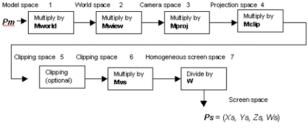
Now let us focus on the description of each transformation stage which is needed.
World matrix Mworld transforms the required vertices from the model space to the world space. This matrix is set as mentioned below −
syntaxCopy
   d3dDevice->SetTransform (D3DTRANSFORMSTATE_WORLD, matrix address)
DirectX assumes that the last column of this matrix is taken as (0,0,0,1). No error is returned if the user specifically mentions the matrix with a different last column.
View matrix Mview transforms vertices from the world space to the camera space. The demonstration of setting up this matrix is set as follows −
syntaxCopy
   d3dDevice->SetTransform (D3DTRANSFORMSTATE_VIEW, matrix address)
Direct3D implementation assumes that the last column of this matrix is (0, 0, 0, 1).
Projection matrix which is also called Mproj transforms vertices from the mentioned camera space to the projection space. The basic syntax of creating the matrix is mentioned below −
syntaxCopy
   d3dDevice->SetTransform (D3DTRANSFORMSTATE_PROJECTION, matrix address)
