- Radar Systems Tutorial
- Radar Systems - Home
- Radar Systems - Overview
- Radar Systems - Range Equation
- Performance Factors
- Radar Systems - Types of Radars
- Radar Systems - Pulse Radar
- Radar Systems - Doppler Effect
- Radar Systems - CW Radar
- Radar Systems - FMCW Radar
- Radar Systems - MTI Radar
- Delay Line Cancellers
- Radar Systems - Tracking Radar
- Antenna Parameters
- Radar Systems - Radar Antennas
- Matched Filter Receiver
- Radar Systems - Radar Displays
- Radar Systems - Duplexers
- Phased Array Antennas
- Radar Systems Useful Resources
- Radar Systems - Quick Guide
- Radar Systems - Useful Resources
- Radar Systems - Discussion
Radar Systems - MTI Radar
If the Radar is used for detecting the movable target, then the Radar should receive only the echo signal due to that movable target. This echo signal is the desired one. However, in practical applications, Radar receives the echo signals due to stationary objects in addition to the echo signal due to that movable target.
The echo signals due to stationary objects (places) such as land and sea are called clutters because these are unwanted signals. Therefore, we have to choose the Radar in such a way that it considers only the echo signal due to movable target but not the clutters.
For this purpose, Radar uses the principle of Doppler Effect for distinguishing the non-stationary targets from stationary objects. This type of Radar is called Moving Target Indicator Radar or simply, MTI Radar.
According to Doppler effect, the frequency of the received signal will increase if the target is moving towards the direction of Radar. Similarly, the frequency of the received signal will decrease if the target is moving away from the Radar.
Types of MTI Radars
We can classify the MTI Radars into the following two types based on the type of transmitter that has been used.
- MTI Radar with Power Amplifier Transmitter
- MTI Radar with Power Oscillator Transmitter
Now, let us discuss about these two MTI Radars one by one.
MTI Radar with Power Amplifier Transmitter
MTI Radar uses single Antenna for both transmission and reception of signals with the help of Duplexer. The block diagram of MTI Radar with power amplifier transmitter is shown in the following figure.
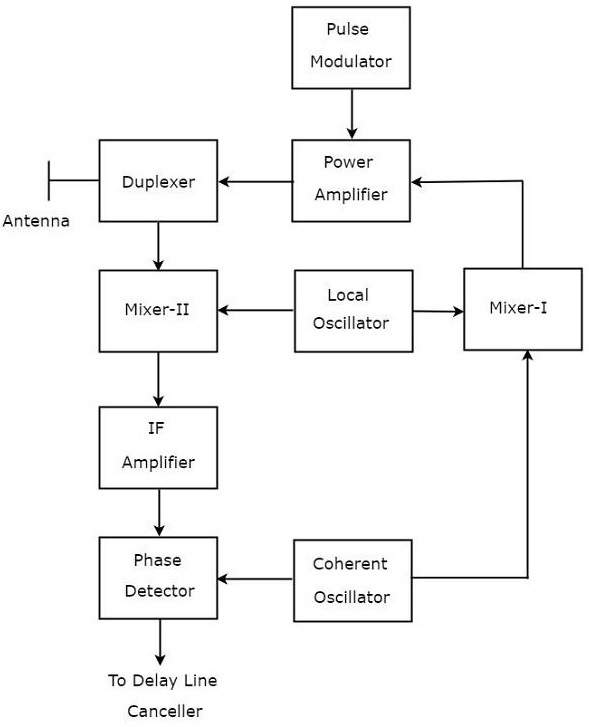
The function of each block of MTI Radar with power amplifier transmitter is mentioned below.
Pulse Modulator − It produces a pulse modulated signal and it is applied to Power Amplifier.
Power Amplifier − It amplifies the power levels of the pulse modulated signal.
Local Oscillator − It produces a signal having stable frequency $f_l$. Hence, it is also called stable Local Oscillator. The output of Local Oscillator is applied to both Mixer-I and Mixer-II.
Coherent Oscillator − It produces a signal having an Intermediate Frequency, $f_c$. This signal is used as the reference signal. The output of Coherent Oscillator is applied to both Mixer-I and Phase Detector.
Mixer-I − Mixer can produce either sum or difference of the frequencies that are applied to it. The signals having frequencies of $f_l$ and $f_c$ are applied to Mixer-I. Here, the Mixer-I is used for producing the output, which is having the frequency $f_l+f_c$.
Duplexer − It is a microwave switch, which connects the Antenna to either the transmitter section or the receiver section based on the requirement. Antenna transmits the signal having frequency $f_l+f_c$ when the duplexer connects the Antenna to power amplifier. Similarly, Antenna receives the signal having frequency of $f_l+f_c\pm f_d$ when the duplexer connects the Antenna to Mixer-II.
Mixer-II − Mixer can produce either sum or difference of the frequencies that are applied to it. The signals having frequencies $f_l+f_c\pm f_d$ and $f_l$ are applied to Mixer-II. Here, the Mixer-II is used for producing the output, which is having the frequency $f_c\pm f_d$.
IF Amplifier − IF amplifier amplifies the Intermediate Frequency (IF) signal. The IF amplifier shown in the figure amplifies the signal having frequency $f_c+f_d$. This amplified signal is applied as an input to Phase detector.
Phase Detector − It is used to produce the output signal having frequency $f_d$ from the applied two input signals, which are having the frequencies of $f_c+f_d$ and $f_c$. The output of phase detector can be connected to Delay line canceller.
MTI Radar with Power Oscillator Transmitter
The block diagram of MTI Radar with power oscillator transmitter looks similar to the block diagram of MTI Radar with power amplifier transmitter. The blocks corresponding to the receiver section will be same in both the block diagrams. Whereas, the blocks corresponding to the transmitter section may differ in both the block diagrams.
The block diagram of MTI Radar with power oscillator transmitter is shown in the following figure.
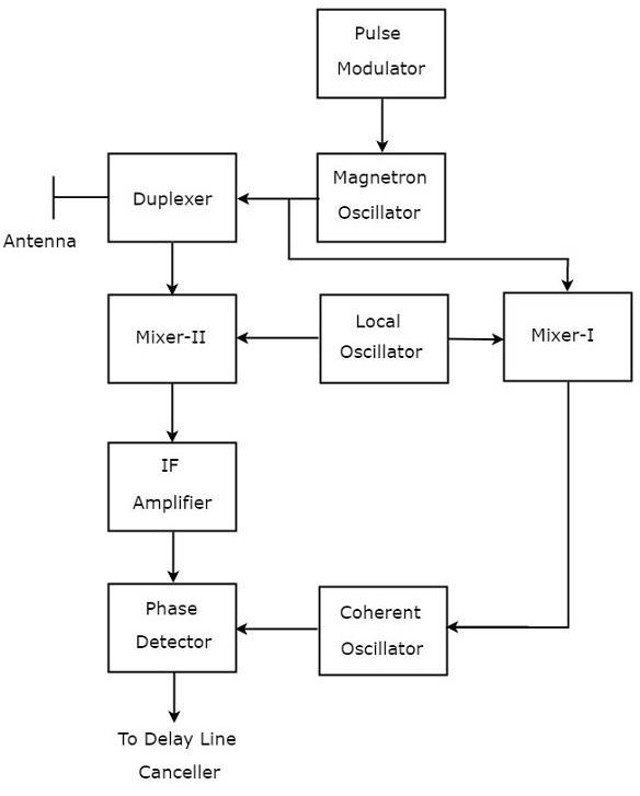
As shown in the figure, MTI Radar uses the single Antenna for both transmission and reception of signals with the help of Duplexer. The operation of MTI Radar with power oscillator transmitter is mentioned below.
The output of Magnetron Oscillator and the output of Local Oscillator are applied to Mixer-I. This will further produce an IF signal, the phase of which is directly related to the phase of the transmitted signal.
The output of Mixer-I is applied to the Coherent Oscillator. Therefore, the phase of Coherent Oscillator output will be locked to the phase of IF signal. This means, the phase of Coherent Oscillator output will also directly relate to the phase of the transmitted signal.
So, the output of Coherent Oscillator can be used as reference signal for comparing the received echo signal with the corresponding transmitted signal using phase detector.
The above tasks will be repeated for every newly transmitted signal.