- Radar Systems Tutorial
- Radar Systems - Home
- Radar Systems - Overview
- Radar Systems - Range Equation
- Performance Factors
- Radar Systems - Types of Radars
- Radar Systems - Pulse Radar
- Radar Systems - Doppler Effect
- Radar Systems - CW Radar
- Radar Systems - FMCW Radar
- Radar Systems - MTI Radar
- Delay Line Cancellers
- Radar Systems - Tracking Radar
- Antenna Parameters
- Radar Systems - Radar Antennas
- Matched Filter Receiver
- Radar Systems - Radar Displays
- Radar Systems - Duplexers
- Phased Array Antennas
- Radar Systems Useful Resources
- Radar Systems - Quick Guide
- Radar Systems - Useful Resources
- Radar Systems - Discussion
Radar Systems - Delay Line Cancellers
In this chapter, we will learn about Delay Line Cancellers in Radar Systems. As the name suggests, delay line introduces a certain amount of delay. So, the delay line is mainly used in Delay line canceller in order to introduce a delay of pulse repetition time.
Delay line canceller is a filter, which eliminates the DC components of echo signals received from stationary targets. This means, it allows the AC components of echo signals received from non-stationary targets, i.e., moving targets.
Types of Delay Line Cancellers
Delay line cancellers can be classified into the following two types based on the number of delay lines that are present in it.
- Single Delay Line Canceller
- Double Delay Line Canceller
In our subsequent sections, we will discuss more about these two Delay line cancellers.
Single Delay Line Canceller
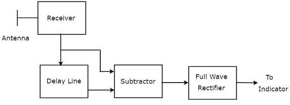
The combination of a delay line and a subtractor is known as Delay line canceller. It is also called single Delay line canceller. The block diagram of MTI receiver with single Delay line canceller is shown in the figure below.
We can write the mathematical equation of the received echo signal after the Doppler effect as −
$$V_1=A\sin\left [ 2\pi f_dt-\phi_0 \right ]\:\:\:\:\:Equation\:1$$
Where,
A is the amplitude of video signal
$f_d$ is the Doppler frequency
$\phi_o$ is the phase shift and it is equal to $4\pi f_tR_o/C$
We will get the output of Delay line canceller, by replacing $t$ by $t-T_P$ in Equation 1.
$$V_2=A\sin\left [ 2\pi f_d\left ( t-T_P\right )-\phi_0 \right ]\:\:\:\:\:Equation\:2$$
Where,
$T_P$ is the pulse repetition time
We will get the subtractor output by subtracting Equation 2 from Equation 1.
$$V_1-V_2=A\sin\left [ 2\pi f_dt-\phi_0 \right ]-A\sin\left [ 2\pi f_d\left ( t-T_P\right )-\phi_0 \right ]$$
$$\Rightarrow V_1-V_2=2A\sin\left [ \frac{ 2\pi f_dt-\phi_0-\left [ 2\pi f_d\left ( t-T_P \right )-\phi_0 \right ]}{2}\right ]\cos\left [ \frac{ 2\pi f_dt-\phi_o+2\pi f_d\left ( t-T_P \right )-\phi_0 }{2}\right ]$$
$$V_1-V_2=2A\sin\left [ \frac{2\pi f_dT_P}{2} \right ]\cos\left [ \frac{2\pi f_d\left ( 2t-T_P \right )-2\phi_0}{2} \right ]$$
$$\Rightarrow V_1-V_2=2A\sin\left [ \pi f_dT_p \right ]\cos\left [ 2\pi f_d\left ( t-\frac{T_P}{2} \right )-\phi_0 \right ]\:\:\:\:\:Equation\:3$$
The output of subtractor is applied as input to Full Wave Rectifier. Therefore, the output of Full Wave Rectifier looks like as shown in the following figure. It is nothing but the frequency response of the single delay line canceller.
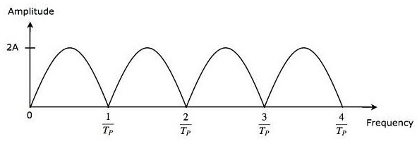
From Equation 3, we can observe that the frequency response of the single delay line canceller becomes zero, when $\pi f_dT_P$ is equal to integer multiples of $\pi$ This means, $\pi f_dT_P$ is equal to $n\pi$ Mathematically, it can be written as
$$\pi f_dT_P=n\pi$$
$$\Rightarrow f_dT_P=n$$
$$\Rightarrow f_d=\frac{n}{T_P}\:\:\:\:\:Equation\:4$$
From Equation 4, we can conclude that the frequency response of the single delay line canceller becomes zero, when Doppler frequency $f_d$ is equal to integer multiples of reciprocal of pulse repetition time $T_P$.
We know the following relation between the pulse repetition time and pulse repetition frequency.
$$f_d=\frac{1}{T_P}$$
$$\Rightarrow \frac{1}{T_P}=f_P\:\:\:\:\:Equation\:5$$
We will get the following equation, by substituting Equation 5 in Equation 4.
$$\Rightarrow f_d=nf_P\:\:\:\:\:Equation\:6$$
From Equation 6, we can conclude that the frequency response of the single delay line canceller becomes zero, when Doppler frequency, $f_d$ is equal to integer multiples of pulse repetition frequency $f_P$.
Blind Speeds
From what we learnt so far, single Delay line canceller eliminates the DC components of echo signals received from stationary targets, when $n$ is equal to zero. In addition to that, it also eliminates the AC components of echo signals received from non-stationary targets, when the Doppler frequency $f_d$ is equal to integer (other than zero) multiples of pulse repetition frequency $f_P$.
So, the relative velocities for which the frequency response of the single delay line canceller becomes zero are called blind speeds. Mathematically, we can write the expression for blind speed $v_n$ as −
$$v_n=\frac{n\lambda}{2T_P}\:\:\:\:\:Equation\:7$$
$$\Rightarrow v_n=\frac{n\lambda f_P}{2}\:\:\:\:\:Equation\:8$$
Where,
$n$ is an integer and it is equal to 1, 2, 3 and so on
$\lambda$ is the operating wavelength
Example Problem
An MTI Radar operates at a frequency of $6GHZ$ with a pulse repetition frequency of $1KHZ$. Find the first, second and third blind speeds of this Radar.
Solution
Given,
The operating frequency of MTI Radar, $f=6GHZ$
Pulse repetition frequency, $f_P=1KHZ$.
Following is the formula for operating wavelength $\lambda$ in terms of operating frequency, f.
$$\lambda=\frac{C}{f}$$
Substitute, $C=3\times10^8m/sec$ and $f=6GHZ$ in the above equation.
$$\lambda=\frac{3\times10^8}{6\times10^9}$$
$$\Rightarrow \lambda=0.05m$$
So, the operating wavelength $\lambda$ is equal to $0.05m$, when the operating frequency f is $6GHZ$.
We know the following formula for blind speed.
$$v_n=\frac{n\lambda f_p}{2}$$
By substituting, $n$=1,2 & 3 in the above equation, we will get the following equations for first, second & third blind speeds respectively.
$$v_1=\frac{1\times \lambda f_p}{2}=\frac{\lambda f_p}{2}$$
$$v_2=\frac{2\times \lambda f_p}{2}=2\left ( \frac{\lambda f_p}{2} \right )=2v_1$$
$$v_3=\frac{3\times \lambda f_p}{2}=3\left ( \frac{\lambda f_p}{2} \right )=3v_1$$
Substitute the values of $\lambda$ and $f_P$ in the equation of first blind speed.
$$v_1=\frac{0.05\times 10^3}{2}$$
$$\Rightarrow v_1=25m/sec$$
Therefore, the first blind speed $v_1$ is equal to $25m/sec$ for the given specifications.
We will get the values of second & third blind speeds as $50m/sec$& $75m/sec$ respectively by substituting the value of 𝑣1 in the equations of second & third blind speeds.
Double Delay Line Canceller
We know that a single delay line canceller consists of a delay line and a subtractor. If two such delay line cancellers are cascaded together, then that combination is called Double delay line canceller. The block diagram of Double delay line canceller is shown in the following figure.
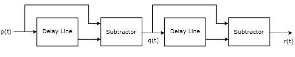
Let $p\left ( t \right )$ and $q\left ( t \right )$ be the input and output of the first delay line canceller. We will get the following mathematical relation from first delay line canceller.
$$q\left ( t \right )=p\left ( t \right )-p\left ( t-T_P \right )\:\:\:\:\:Equation\:9$$
The output of the first delay line canceller is applied as an input to the second delay line canceller. Hence, $q\left ( t \right )$ will be the input of the second delay line canceller. Let $r\left ( t \right )$ be the output of the second delay line canceller. We will get the following mathematical relation from the second delay line canceller.
$$r\left ( t \right )=q\left ( t \right )-q\left ( t-T_P \right )\:\:\:\:\:Equation\:10$$
Replace $t$ by $t-T_P$ in Equation 9.
$$q\left ( t-T_P \right )=p\left ( t-T_P \right )-p\left ( t-T_P-T_P \right )$$
$$q\left ( t-T_P \right )=p\left ( t-T_P \right )-p\left ( t-2T_P \right )\:\:\:\:\:Equation\:11$$
Substitute, Equation 9 and Equation 11 in Equation 10.
$$r\left ( t \right )=p\left ( t \right )-p\left ( t-T_P \right )-\left [ p\left ( t-T_P \right )-p\left ( t-2T_P \right ) \right ]$$
$$\Rightarrow r\left ( t \right )=p\left ( t \right )-2p\left ( t-T_P \right )+p\left ( t-2T_P \right )\:\:\:\:\:Equation\:12$$
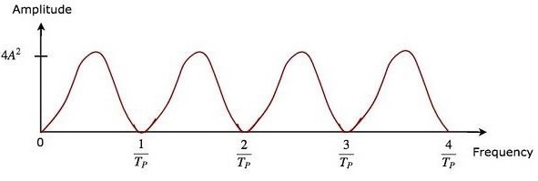
The advantage of double delay line canceller is that it rejects the clutter broadly. The output of two delay line cancellers, which are cascaded, will be equal to the square of the output of single delay line canceller.
So, the magnitude of output of double delay line canceller, which is present at MTI Radar receiver will be equal to $4A^2\left ( \sin\left [ \pi f_dT_P \right ] \right )^2$.
The frequency response characteristics of both double delay line canceller and the cascaded combination of two delay line cancellers are the same. The advantage of time domain delay line canceller is that it can be operated for all frequency ranges.